
Pressure relief device, system, and method

a pressure relief device and pressure relief technology, applied in the direction of transportation and packaging, functional valve types, borehole/well accessories, etc., can solve problems such as subsequent breaking

Active Publication Date: 2013-05-23
OKLAHOMA SAFETY EQUIP
View PDF28 Cites 35 Cited by
  • Summary
  • Abstract
  • Description
  • Claims
  • Application Information

AI Technical Summary

Benefits of technology

The present invention relates to a pressure relief device for use in hydraulic fracturing systems. The device is designed to prevent damage to the system caused by high pressure spikes and to allow for safe and effective operation. The device includes a rupture disc that can burst to release pressure when the pressure reaches a certain level, and a controller that can detect the burst and take appropriate action, such as shutting down the system to prevent damage. The technical effect of this invention is to provide a reliable and effective means for protecting hydraulic fracturing systems from pressure spikes and ensuring safe operation.

Problems solved by technology

The liquid will continue to flow into these fractures, creating fissures.
However, pressure spikes can occur throughout the system that if sufficiently high could cause piping to break or weaken, ultimately leading to subsequent breaking due to fatigue.

Method used


Image

  • Pressure relief device, system, and method
  • Pressure relief device, system, and method
  • Pressure relief device, system, and method

Examples


Embodiment Construction

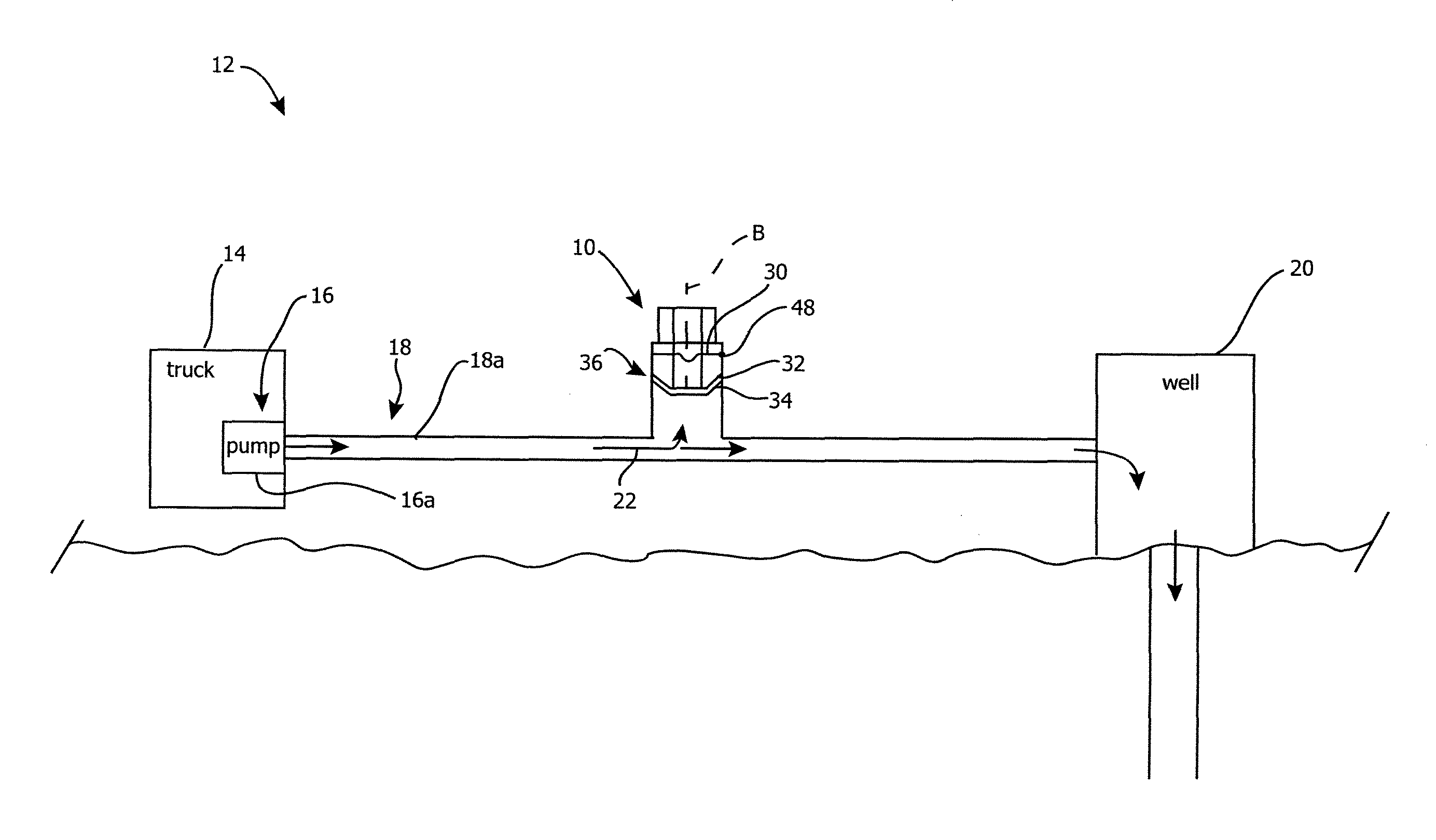
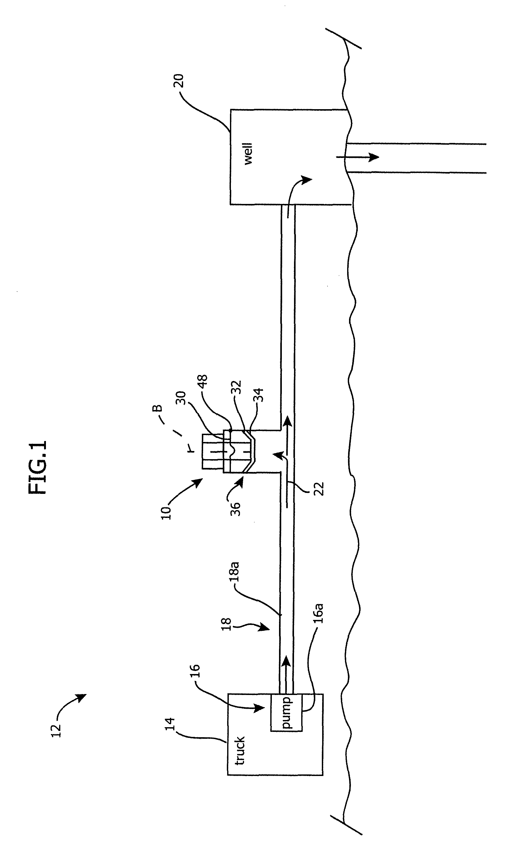
[0025]With reference to FIG. 1, a pressure relief device 10 is provided for relieving high pressure within a hydraulic fracturing, or fracking, system 12. The pressure relief device 10 can be connected as desired at different locations along the system 12 where pressure relief may be needed. The system 12 includes a pressurized fracturing fluid source which typically includes a fluid delivery truck 14 having a fluid end 16 that has a pump 16a for pressurizing the fracturing fluid. The pump 16a of the truck 14 is connected to a delivery line 18, which can include flexible and / or rigid pipes 18a, which are connected to a well 20. Typically, rigid pipes 18a will be utilized between the pump 16a and the well 20, while lower pressure, flexible conduits can be used as feed lines to the pump 16a. A fracturing fluid media 22, including water, sand, and chemicals, is pumped under pressure, e.g., approximately 5,500-16,000 psig, from the truck 14 into the well 20 at high pressure to perform ...


PUM


Abstract

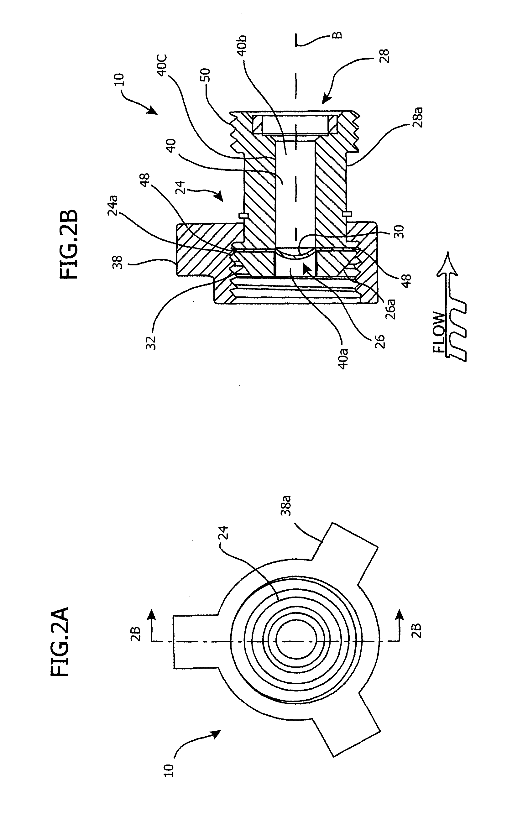
A pressure relief device and a hydraulic fracturing system having a pressure relief device are provided. In one form, the pressure relief device has a valve body with a linearly extending throughbore between the inlet and outlet thereof. A rupture disc is secured in the valve body so that a frangible dome wall portion thereof has a reverse-acting orientation in the valve body bore. The hydraulic fracturing system includes a pump and a delivery line that receives pressurized fracturing fluid from the pump and delivers it to a well. A pressure relief device is installed along the delivery line. A sensor detects fluid flow downstream of the pressure relief device which allows the pump to be shut down when the downstream fluid flow is detected. The pressure relief device can have a body with a domed rupture disc and the sensor therein.

Description

CROSS REFERENCE TO RELATED APPLICATION[0001]This application claims benefit under 35 U.S.C. §119 (e) to United States Provisional Application No. 61 / 556,773 entitled “Pressure Relief Device, System, and Method” filed Nov. 7, 2011, having attorney docket number 9205-100791-US, the contents of which are incorporated herein by reference in its entirety.FIELD OF THE INVENTION[0002]The present invention relates to a pressure relief device, system, and method and, more particularly, to a rupture disc device for relieving pressure in a hydraulic fracturing fluid delivery system.BACKGROUND OF THE INVENTION[0003]Hydraulic fracturing, or fracking, is a process used to recover natural gas, oil, or other fossil fuels from rock layers deep below ground level. A typical hydraulic fracturing process includes multiple trucks pumping a pressurized liquid mixture of water, sand, and chemicals into a wellhead above the surface, which feeds into a wellbore extending below the surface to the desired dep...

Claims


Application Information

Patent Timeline
IPC IPC(8): E21B43/26
CPCE21B34/063E21B43/26F16K17/1606Y10T137/1692E21B43/2607
Inventor BANKS, DAVID WAYNEEVANS, ROBERT FRANKSTOCKSTILL, DOYLE G.
Owner OKLAHOMA SAFETY EQUIP
Learn More