Power transmission system, vehicle and power supply facility

a technology for power transmission systems and vehicles, applied in charging stations, electric devices, transportation and packaging, etc., can solve the problems of driving up costs in proportion, user cannot immediately determine whether the current position is appropriate for charging, etc., and achieve the effect of easy visual knowledg

Inactive Publication Date: 2013-05-23
TOYOTA JIDOSHA KK
View PDF11 Cites 94 Cited by
  • Summary
  • Abstract
  • Description
  • Claims
  • Application Information

AI Technical Summary

Benefits of technology

[0014]In the above-mentioned aspects of the invention, power is transmitted from the power supply facility to the vehicle in a contactless manner. The distance between the power transmission unit of the power supply facility and the power receiving unit of the vehicle is detected, and the display unit displays the graphic in the display pattern that varies in accordance with the distance detected by the detection unit. As a result, the user of the vehicle can

Problems solved by technology

However, although a relative position between the power supply device mark and the power receiving unit mark is displayed in the power reception guidance device display, the user cannot ascertain immediately whether the current position is a position appropriate for charging or not.
Instal

Method used


Image

  • Power transmission system, vehicle and power supply facility
  • Power transmission system, vehicle and power supply facility
  • Power transmission system, vehicle and power supply facility

Examples


embodiment 1

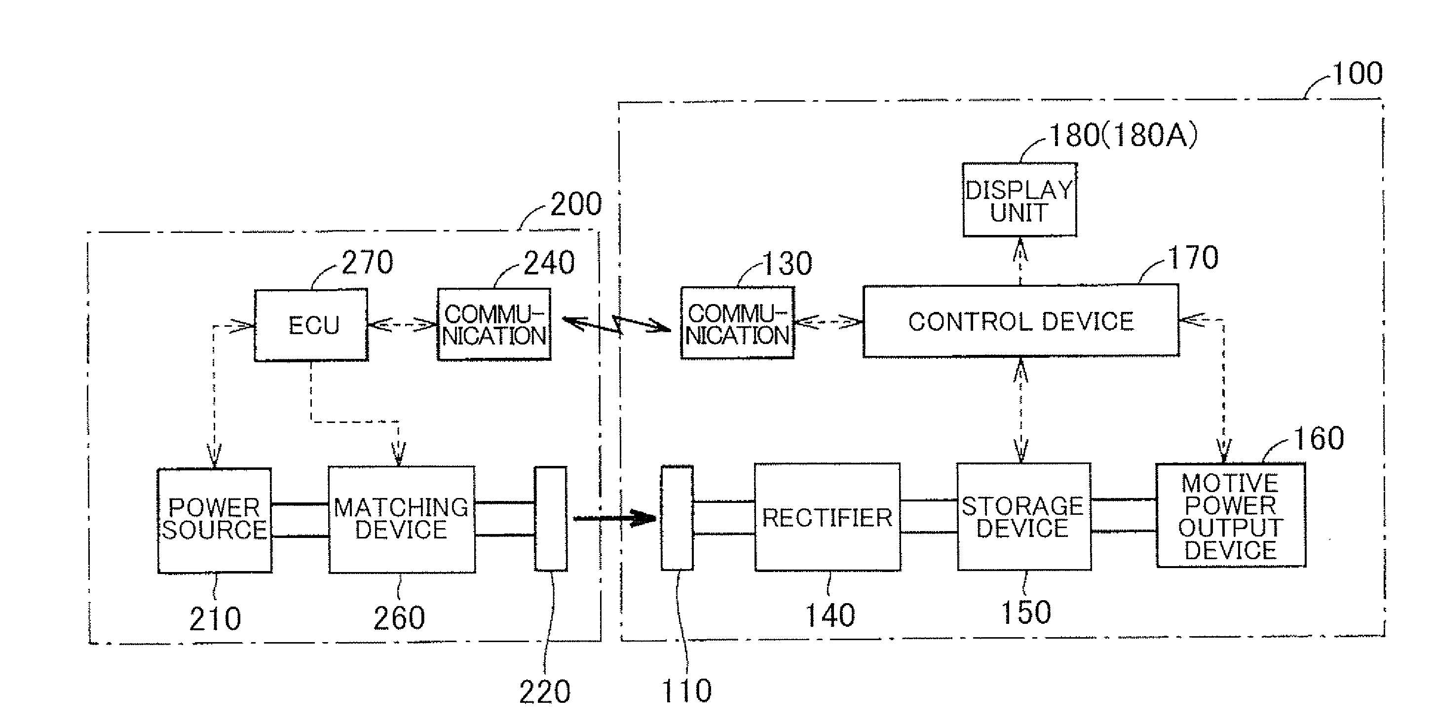
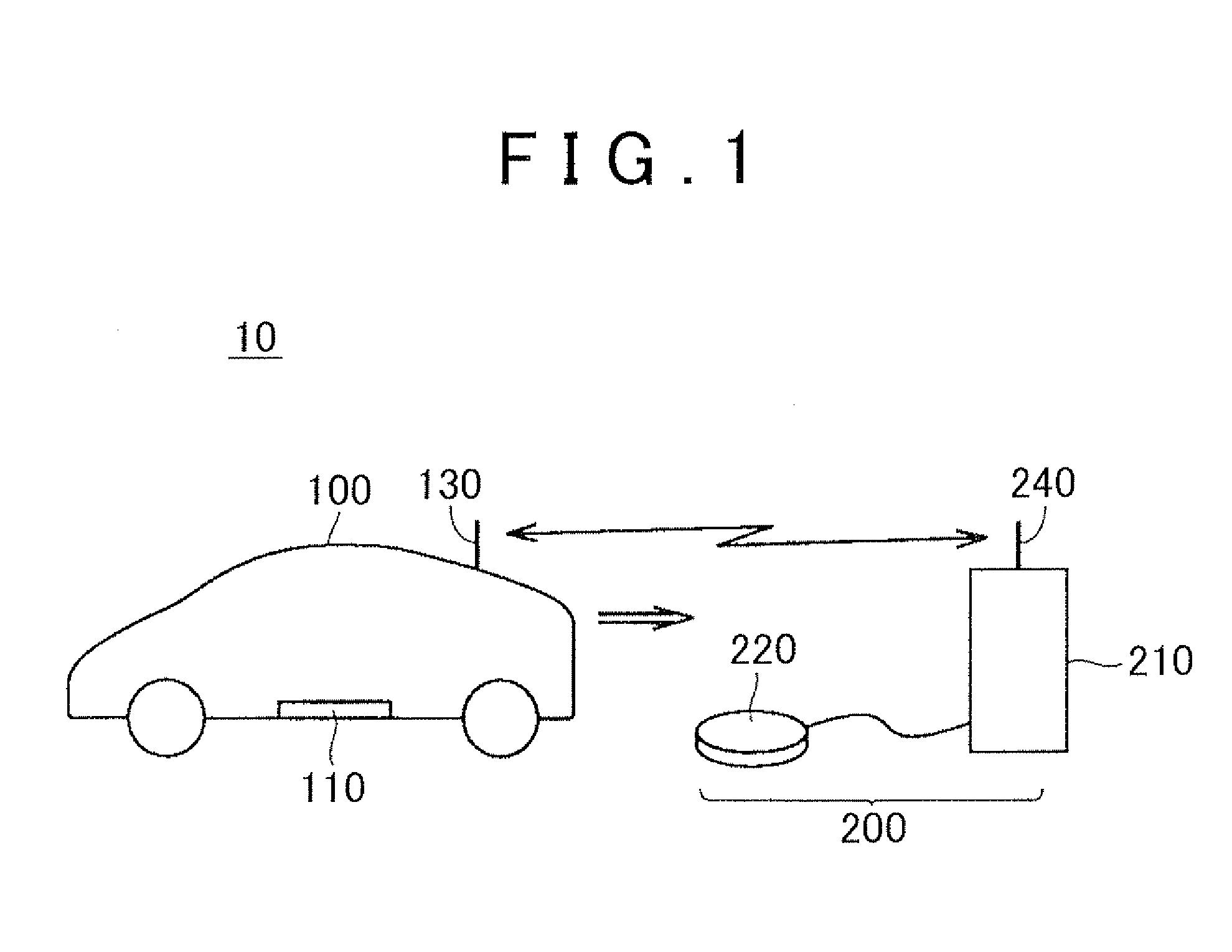
[0033]FIG. 1 is an overall configuration diagram of a vehicle power supply system in Embodiment 1 of the invention. With reference to FIG. 1, a vehicle power supply system 10 is provided with a vehicle 100 and a power supply facility 200. The vehicle 100 has a power receiving unit 110 and a communication unit 130.

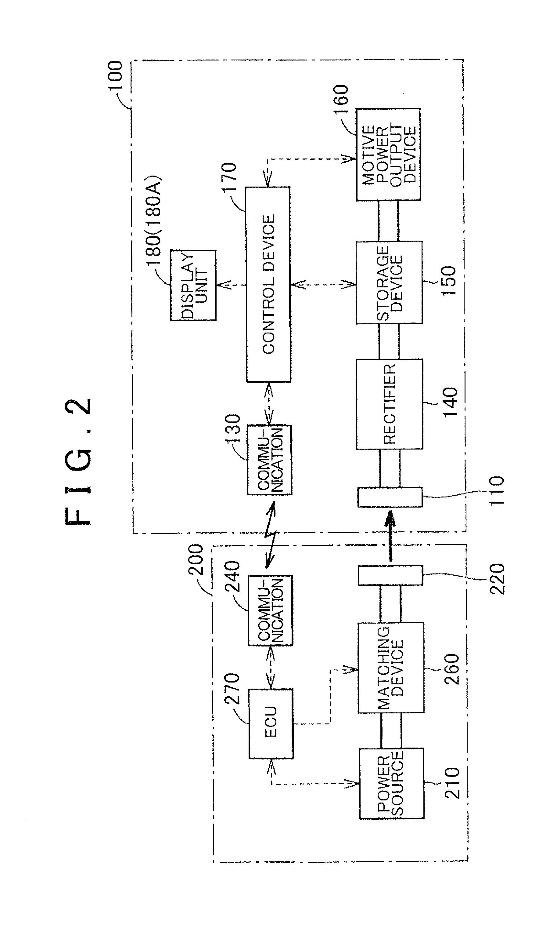
[0034]The power receiving unit 110 is disposed at the bottom face of the vehicle body. The power receiving unit 110 receives, in a contactless manner, through of an electromagnetic field, high-frequency alternating current (AC) power that is outputted by a power transmission unit 220 (described below) of the power supply facility 200. The configuration of the power receiving unit 110 will be explained further on together with the configuration of the power transmission unit 220 and power transmission from the power transmission unit 220 to the power receiving unit 110. The communication unit 130 is a communication interface for communication of the vehicle 100 with the powe...

embodiment 2

[0094]In Embodiment 2, notification sound is generated according to changes in the display pattern by the display unit 180 (180A), in addition to the visual display by the display unit 180 (180A).

[0095]FIG. 15 is a functional block diagram for explaining the configuration of the vehicle in Embodiment 2. With reference to FIG. 15, a vehicle 100A in Embodiment 2 further has a notification unit 190 in the configuration of the vehicle 100 in Embodiment 1 illustrated in FIG. 2.

[0096]The notification unit 190 generates a notification sound according to changes in the display pattern by the display unit 180 (180A). As an example, the notification unit 190 lengthens the duration of the notification sound in a case where the distance information display section 186 indicates that the distance between the power transmission unit 220 and the power receiving unit 110 is relatively large, as illustrated in FIG. 3. Specifically, one notification sound may be caused to sound for a longer time, or ...


PUM


Abstract

Power is transmitted from a power supply facility to a vehicle in a contact-less manner. A control device detects a distance between a power transmission unit of the power supply facility and a power receiving unit of the vehicle. A display unit displays a graphic in a display pattern which varies in accordance with the distance detected by the detection unit.

Description

INCORPORATION BY REFERENCE[0001]The disclosure of Japanese Patent Application No. 2011-252821 filed on Nov. 18, 2011 including the specification, drawings and abstract is incorporated herein by reference in its entirety.BACKGROUND OF THE INVENTION[0002]1. Field of the Invention[0003]The invention relates to a power transmission system, a vehicle, and a power supply facility. In particular, the invention relates to a power transmission system in which power is transmitted from a power supply facility to a vehicle in a contact-less manner, relates to a vehicle that receives power from a power supply facility in a contact-less manner, and relates to a power supply facility that supplies power to a vehicle in a contact-less manner.[0004]2. Description of the Related Art[0005]Contact-less wireless power transmission that does not use power source cords or power transmission cables has received attention in recent years. Wireless power transmission has been proposed for use in electric au...

Claims


Application Information

Patent Timeline
IPC IPC(8): H02J7/00B60L3/00
CPCH02J7/0047B60L11/182Y02T90/122Y02T90/14Y02T10/7005Y02T10/7072B60L53/126B60L53/122Y02T10/70Y02T90/12
Inventor ICHIKAWA, SHINJI
Owner TOYOTA JIDOSHA KK
Why Eureka
Try Eureka