Barrier boom implemented as bendable boom of a vehicle barrier

a vehicle barrier and boom technology, applied in roadways, traffic restrictions, roads, etc., can solve the problems of reducing the length of the barrier boom that can be obtained, the negative impact of dimensioning and costs, and the high so as to reduce the production cost, reduce the loading of the drive of the vehicle barrier, and the effect of large installation length

Active Publication Date: 2013-05-30
SKIDATA AG
View PDF5 Cites 5 Cited by
  • Summary
  • Abstract
  • Description
  • Claims
  • Application Information

AI Technical Summary

Benefits of technology

[0014]In the case where a profile element is arranged in the interior of the first barrier boom section along its longitudinal axis and provision is made on at least one inner surface of this barrier boom section for an LED strip, the profile element is preferably made of transparent plastic and optionally encompasses structures which, in case where provision is made for a plurality of LED bands, guide the light that is created in the direction of the arriving vehicles; that is, in the direction toward the side of the barrier boom that faces the arriving vehicles. In the case where provision is made for only one LED band, these structures also direct the light which is created by the LED strip in the direction of the arriving vehicles. As an alternative or in addition to these structures which direct the light toward the arriving vehicles, the surface of the profile element can encompass an amorphous structure that makes it possible to scatter the incident light and thus provide a good illumination of the first barrier boom section.
[0015]Due to the desig

Problems solved by technology

Due to the required chain, barrier booms which are implemented in this manner disadvantageously encompass a relatively high weight, which leads to limitations in the length of the barrier boom that can be obtained, and to a high loading of the drive of the vehicle barrier.
Depending on the weight of the chain, a high performance drive is also required, which has a negative impact on the dimensioning and the costs.
A further disadvantage of the vehicle barriers which are implemented in this manne

Method used


Image

  • Barrier boom implemented as bendable boom of a vehicle barrier
  • Barrier boom implemented as bendable boom of a vehicle barrier
  • Barrier boom implemented as bendable boom of a vehicle barrier

Examples


Embodiment Construction

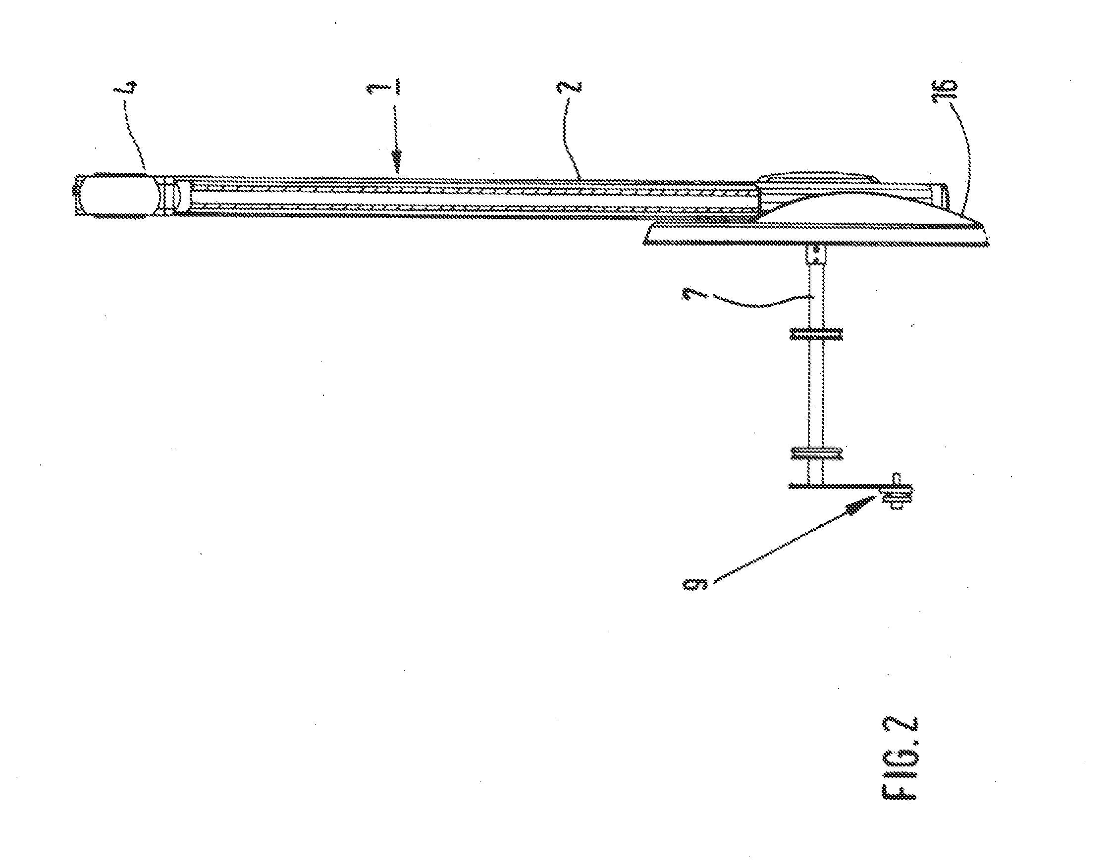
[0020]The preferred embodiments of the present invention will now be described with reference to FIGS. 1 and 2 of the drawings. Identical elements in the two figures are designated with the same reference numerals.

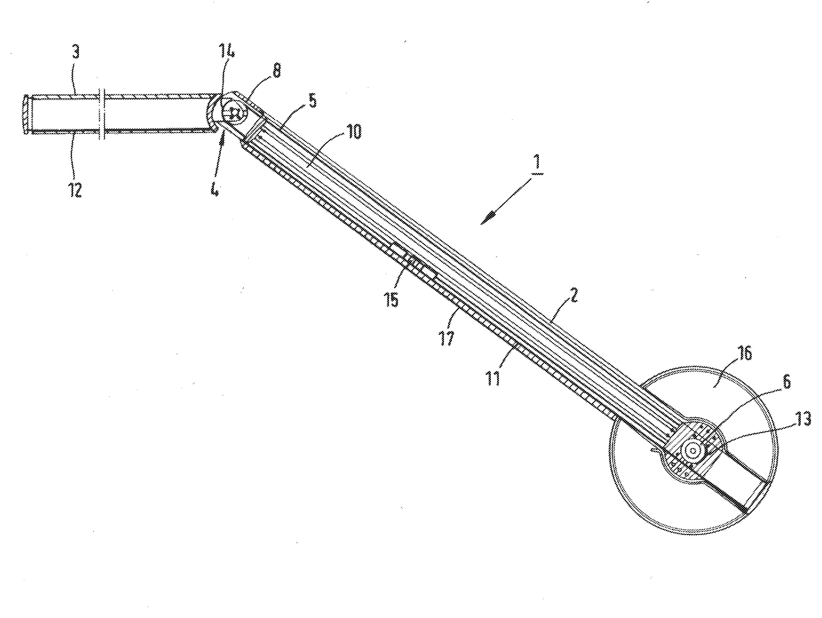
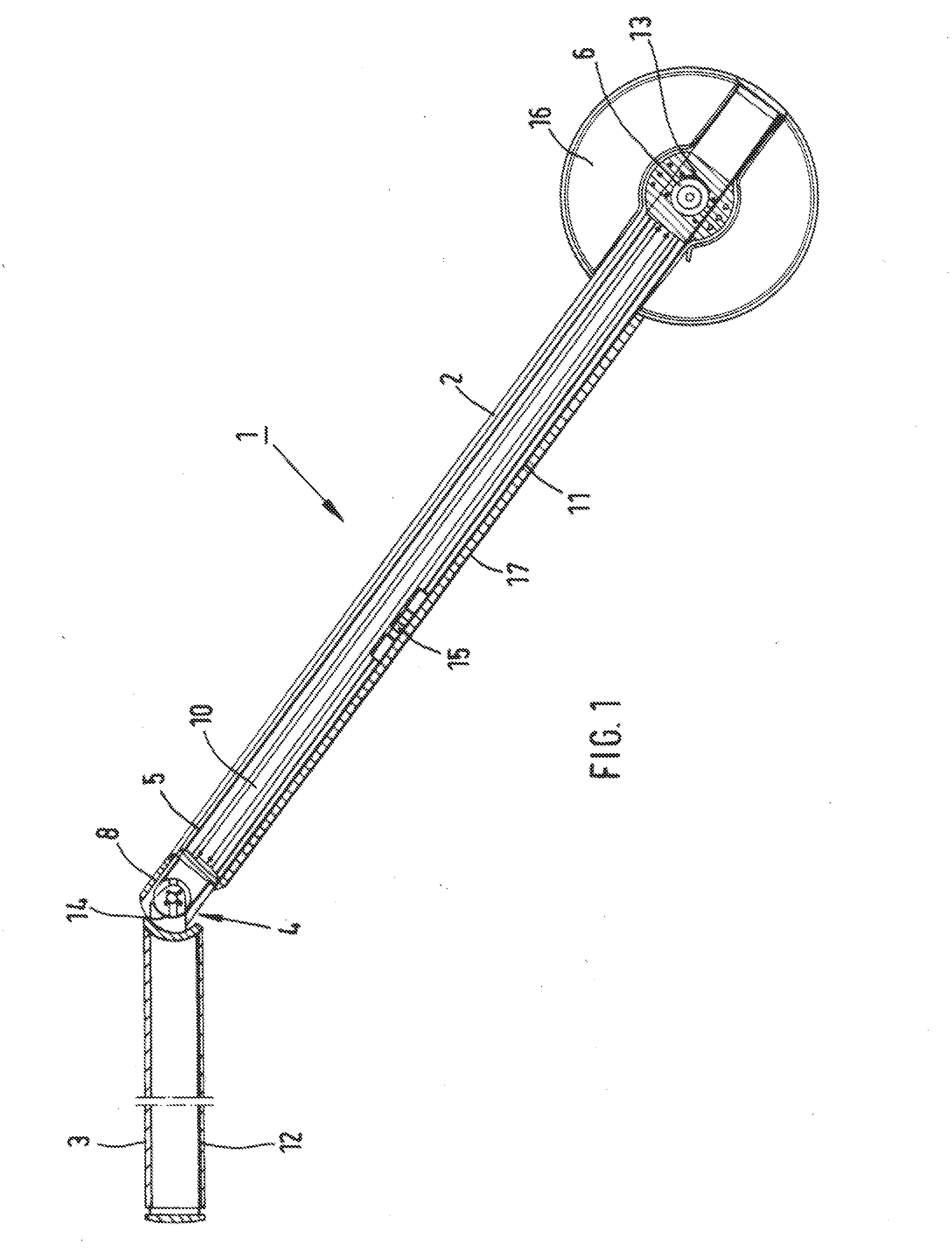
[0021]FIG. 1 illustrates a barrier boom 1, which is implemented as a bendable boom, designed to serve as a vehicle barrier, that can be illuminated by LEDs. The barrier boom 1 comprises a first barrier boom section 2, which is connected to the drive for pivoting the barrier boom 1 between the blocked and the open position, and a second barrier boom section 3, which is connected to the first barrier boom section 2 via a pivot or articulated joint 4 having a horizontal pivot axis.

[0022]To maintain, the second barrier boom section 3 in horizontal position, provision is made for a cord 5, which is arranged in the first barrier boom section 2 parallel to the longitudinal axis of this section 2 and which is tightened and clamped around two cord guide rollers 6, 8. To increase th...


PUM


Abstract

A bendable barrier boom (1) designed to serve as a vehicle barrier, comprises a boom column, a barrier boom (1), and a drive for pivoting the barrier boom (1) between the blocked and the open position. The barrier boom includes a first barrier boom section (2), which is connected to the drive for pivoting the barrier boom (1), and a second barrier boom section (3), which is connected to the first barrier boom section (2) via an articulated joint (4). To maintain the second barrier boom section (3) in the horizontal position, provision is made for a cord (5) arranged in the first barrier boom section (2) parallel to its longitudinal axis that is tightened and clamped around two guide rollers (6, 8). The cord (5) and guide rollers (6, 8) operate to maintain the second boom section in the horizontal position.

Description

BACKGROUND OF THE INVENTION[0001]The invention relates to a bendable barrier boom arrangement designed to serve as a vehicle barrier. This barrier boom arrangement comprises a boom column, a barrier boom and a drive for pivoting the barrier boom between the blocked and the open position.[0002]Barrier booms, which are implemented as bendable booms, are used in particular as parking barriers for controlling the entrance and exit of parking areas, as well as vehicle barriers for operating toll booths. Bendable booms are particularly suitable when the available overall height for the installation of a common, single barrier boom, which is implemented in one piece, is not sufficient. They encompass two barrier boom sections and an articulated joint that is pivoted about a horizontal axis and which connects the two barrier boom sections to one another. One of the two barrier boom sections is connected to the drive for pivoting the barrier boom up and down.[0003]The barrier boom section wh...

Claims


Application Information

Patent Timeline
IPC IPC(8): E01F13/06
CPCE01F13/06
Inventor MELKES, MARIOSCHIEREN, JURGEN
Owner SKIDATA AG
Why Eureka
Try Eureka