
Omnidirectional vehicle

a technology of omnidirectional vehicles and sub wheels, which is applied in the direction of cycle stands, cycle equipment, cycle, etc., can solve the problems of unstable traction of sub wheels and the likelihood of failure of passengers in moving operations, and achieve the effect of preventing foreign substances

Active Publication Date: 2013-05-30
HONDA MOTOR CO LTD
View PDF7 Cites 14 Cited by
  • Summary
  • Abstract
  • Description
  • Claims
  • Application Information

AI Technical Summary

Benefits of technology

The present invention relates to a device for stabilizing the traction of a sub wheel in a vehicle. The device includes a sub wheel that moves around the center of rotation of the main wheel, so that when the vehicle body frame tilts, the pressure of the sub wheel against the ground remains constant. This reduces the change in traction of the sub wheel and ensures smooth operation. Additionally, the device includes a cover that prevents foreign substances from entering the main wheel and a bifurcated-shaped branching portion that allows for easy insertion of an arm member. These features further enhance the stability and reliability of the device.

Problems solved by technology

WO 2008 / 139740, however, the traction of the sub wheel becomes unstable particularly when the vehicle body largely inclines in the anteroposterior direction.
Furthermore, the grounded state and the ungrounded state of the sub wheel is changed by passenger's manipulation, and therefore the passenger is likely to be unsuccessful in performing a moving operation such as a turn intended by the passenger by erroneous manipulation.

Method used


Image

  • Omnidirectional vehicle
  • Omnidirectional vehicle
  • Omnidirectional vehicle

Examples


Embodiment Construction

[0022]One embodiment of the present invention will be described below with reference to FIGS. 1 to 5.

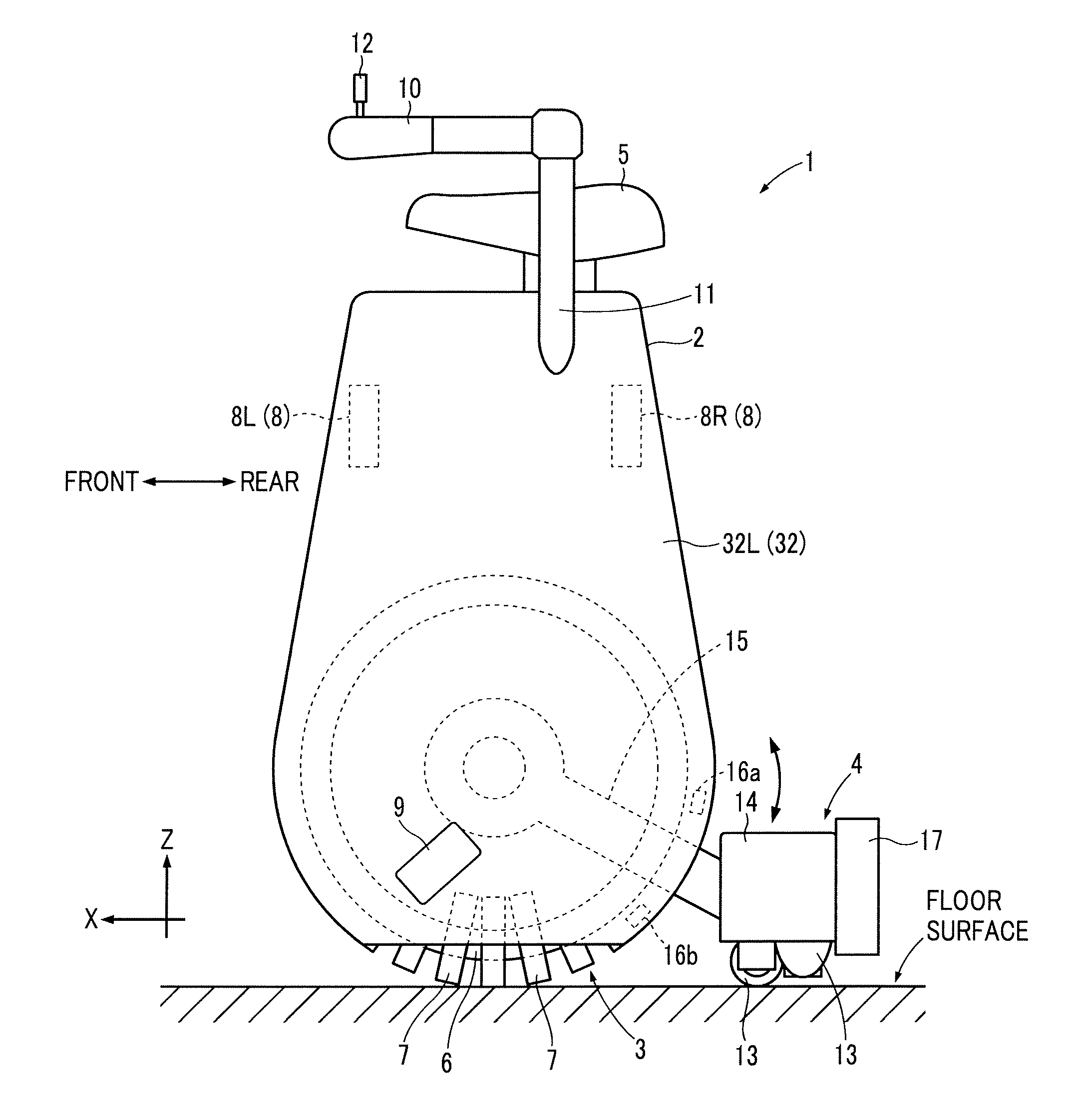
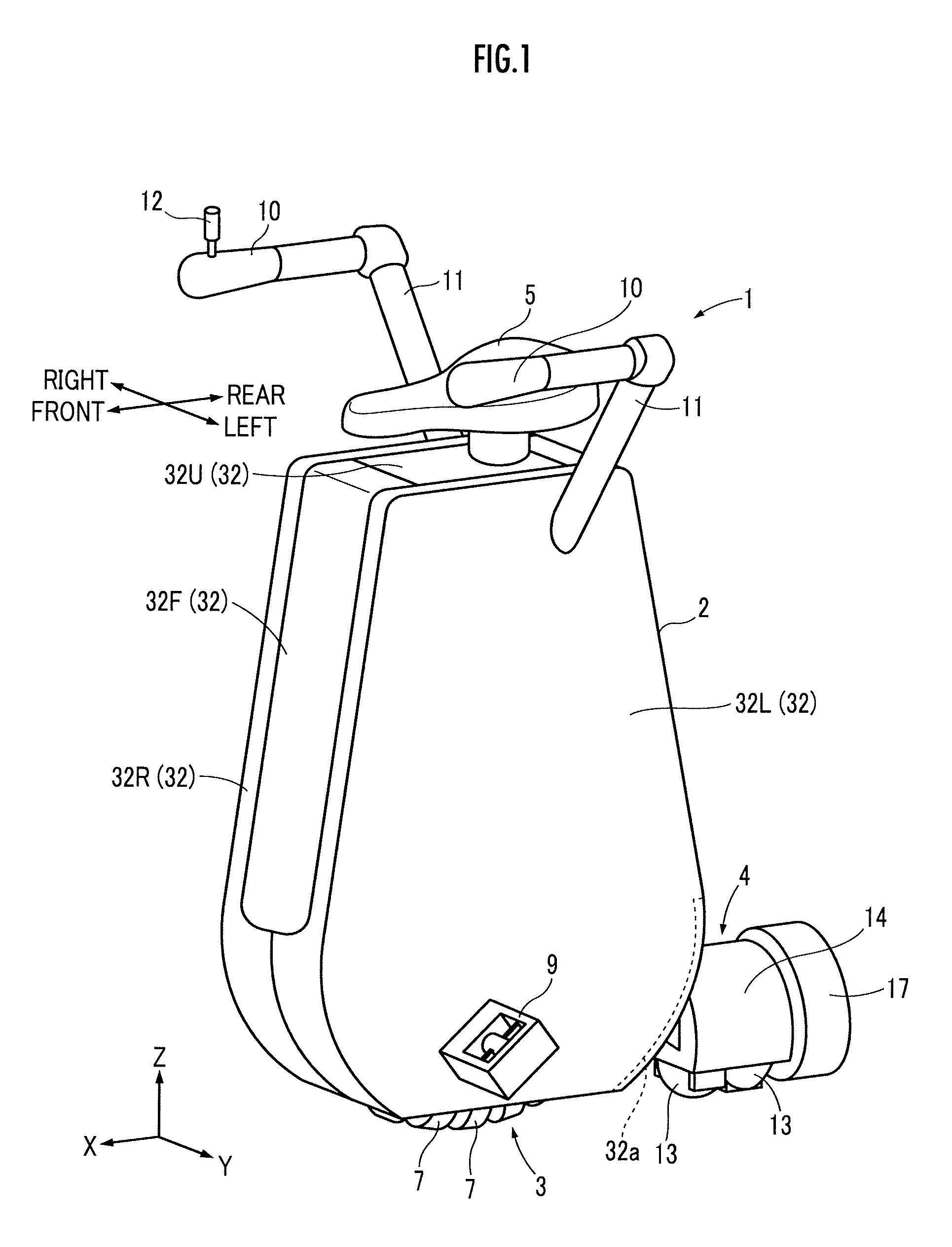
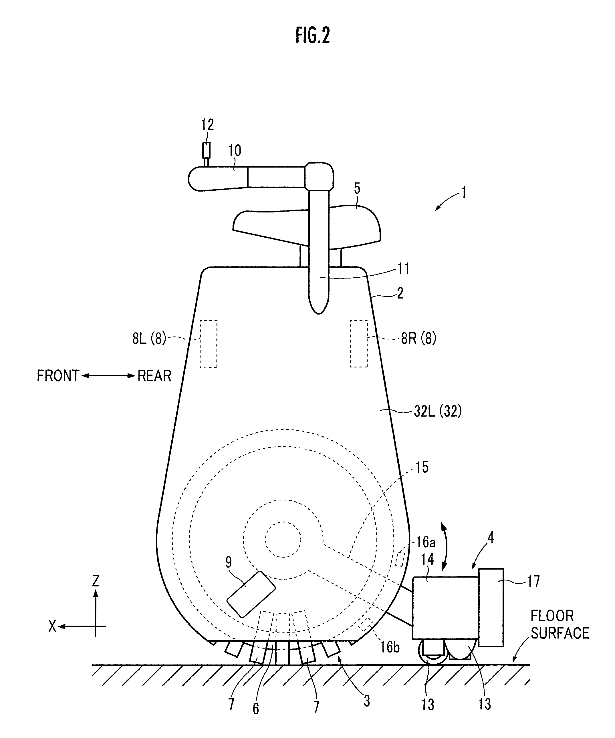
[0023]As illustrated in FIGS. 1 and 2, an omnidirectional vehicle 1 (hereinafter, simply referred to as “vehicle 1” in some cases) of this embodiment includes a base 2, a first moving operation unit 3 and a second moving operation unit 4 movable on a floor surface, and a passenger-riding portion 5 which a passenger rides.

[0024]The first moving operation unit 3 includes an annular core 6 (hereinafter, referred to as “circular core 6”) illustrated in FIG. 2 and a plurality of annular rollers 7 mounted on the circular core 6 so as to be arranged at equal angular intervals in the circumferential direction (the direction about the central axis) of the circular core 6. Each roller 7 is externally inserted into the circular core 6 with its central axis of rotation oriented in the circumferential direction of the circular core 6. Then, each roller 7 is integrally rotatable with the circular ...


PUM


Abstract

An omnidirectional vehicle 1 includes: a main wheel 3 which is able to be driven in all directions; a base 2 which supports the main wheel 3; and a sub wheel 4 which is connected to the base 2 via an arm 15 and is grounded at a position apart from the ground contact point of the main wheel 3. The sub wheel 4 is attached so as to circularly move about the center of rotation of the main wheel 3.

Description

BACKGROUND OF THE INVENTION[0001]1. Field of the Invention[0002]The present invention relates to an omnidirectional vehicle.[0003]2. Description of the Related Art[0004]International Publication No. WO 2008 / 132779 discloses an omnidirectional moving apparatus, in which a main wheel is arranged between rotating members to which a plurality of free rollers are concentrically attached and the main wheel is adapted to be movable in all directions by driving the main wheel using a lateral force of the free rollers, and an omnidirectional vehicle using the omnidirectional moving apparatus.[0005]In addition, International Publication No. WO 2008 / 139740 discloses an omnidirectional vehicle (a conveyance) having sub wheels (auxiliary wheels) each of which is able to contact with the ground at a position apart from the ground contact point of a main wheel (traveling drive wheel) which is able to be driven in all directions so as to be able to turn in a small turning radius. The sub wheel is r...

Claims


Application Information

Patent Timeline
IPC IPC(8): B62D15/00
CPCB62D15/00B62K17/00B62K1/00B60B19/00B62H1/12
Inventor KAMIYAMA, NOZOMIMUTOH, YUSUKE
Owner HONDA MOTOR CO LTD
Learn More