
Substrate accommodation device

a technology for a substrate and a housing device, which is applied in the direction of photomechanical treatment, instruments, separation processes, etc., can solve the problems that the introduction of inert gas into the accommodation vessel may not be sufficient to solve the problem of foreign substances, and achieve the effect of effectively preventing foreign substances from adhering to the substra

Inactive Publication Date: 2012-12-27
TOKYO ELECTRON LTD
View PDF12 Cites 2 Cited by
  • Summary
  • Abstract
  • Description
  • Claims
  • Application Information

AI Technical Summary

Benefits of technology

[0023]In accordance with the illustrative embodiment, it is possible to effectively prevent a foreign substance from adhering to a substrate in the substrate accommodation device. Further, one of the state sensor, the particle charging unit, and the temperature controller or a combination of two or more thereof may be provided in the substrate accommodation device depending on the environment where the substrate accommodation device is used. Hence, it is possible to effectively prevent the foreign substance from adhering to a substrate in the substrate accommodation device depending on the environment, without waste in equipment.

Problems solved by technology

In the conventional accommodation vessels, however, using the ventilator having the filter or diffusing and introducing the inert gas into the accommodation vessel may not be a sufficient solution against the problem of foreign substances depending on the environment (e.g., cleanness, room temperature, dryness, etc.) where the accommodation vessels are used.

Method used


Image

  • Substrate accommodation device
  • Substrate accommodation device
  • Substrate accommodation device

Examples


Embodiment Construction

[0036]Hereinafter, an illustrative embodiment will be described in detail with reference to the accompanying drawings. Through the specification and drawings, parts having substantially the same functions and configurations will be assigned the same reference numerals and redundant description thereof will be omitted.

[0037](Configuration of Substrate Accommodation Device)

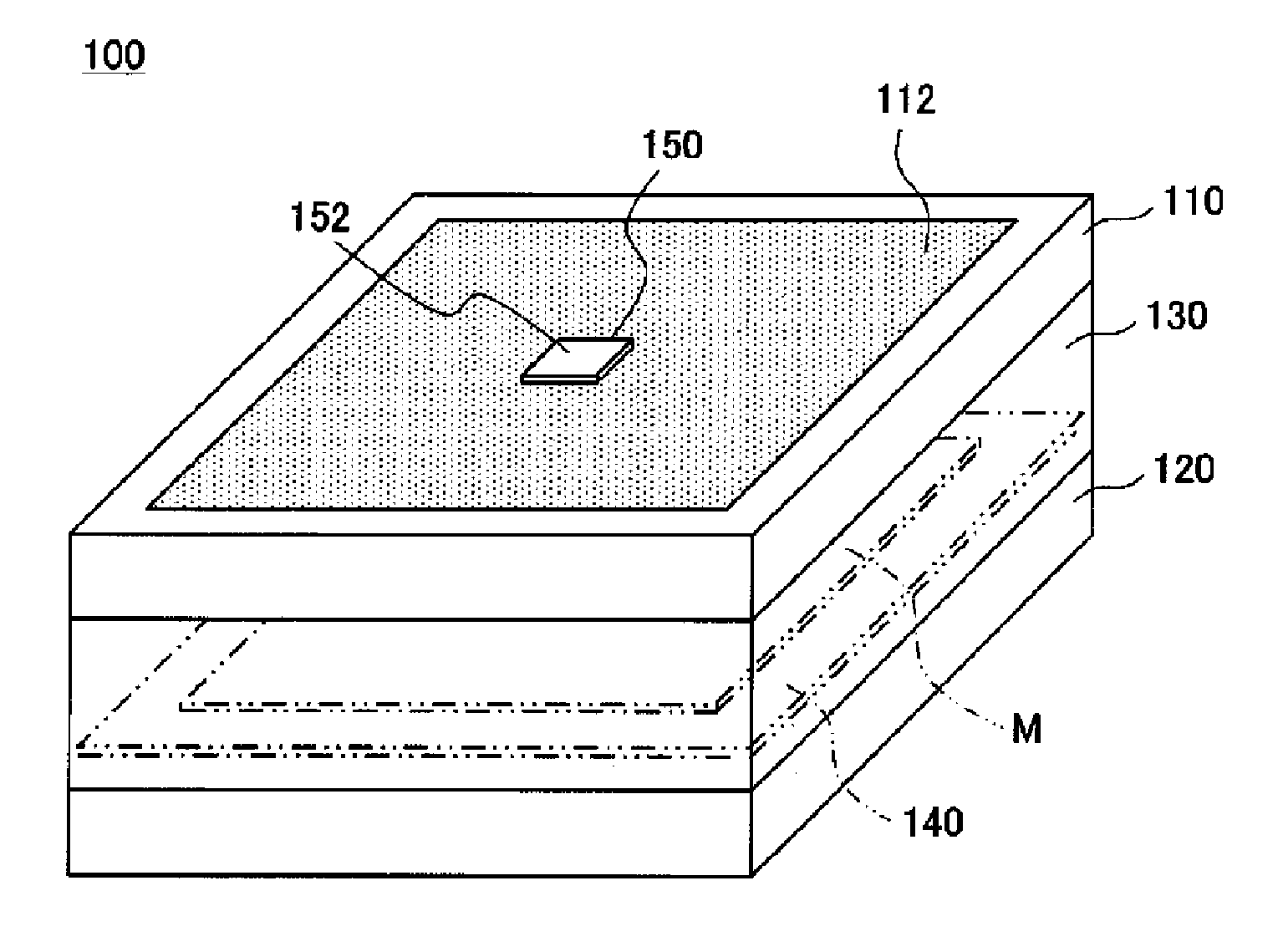
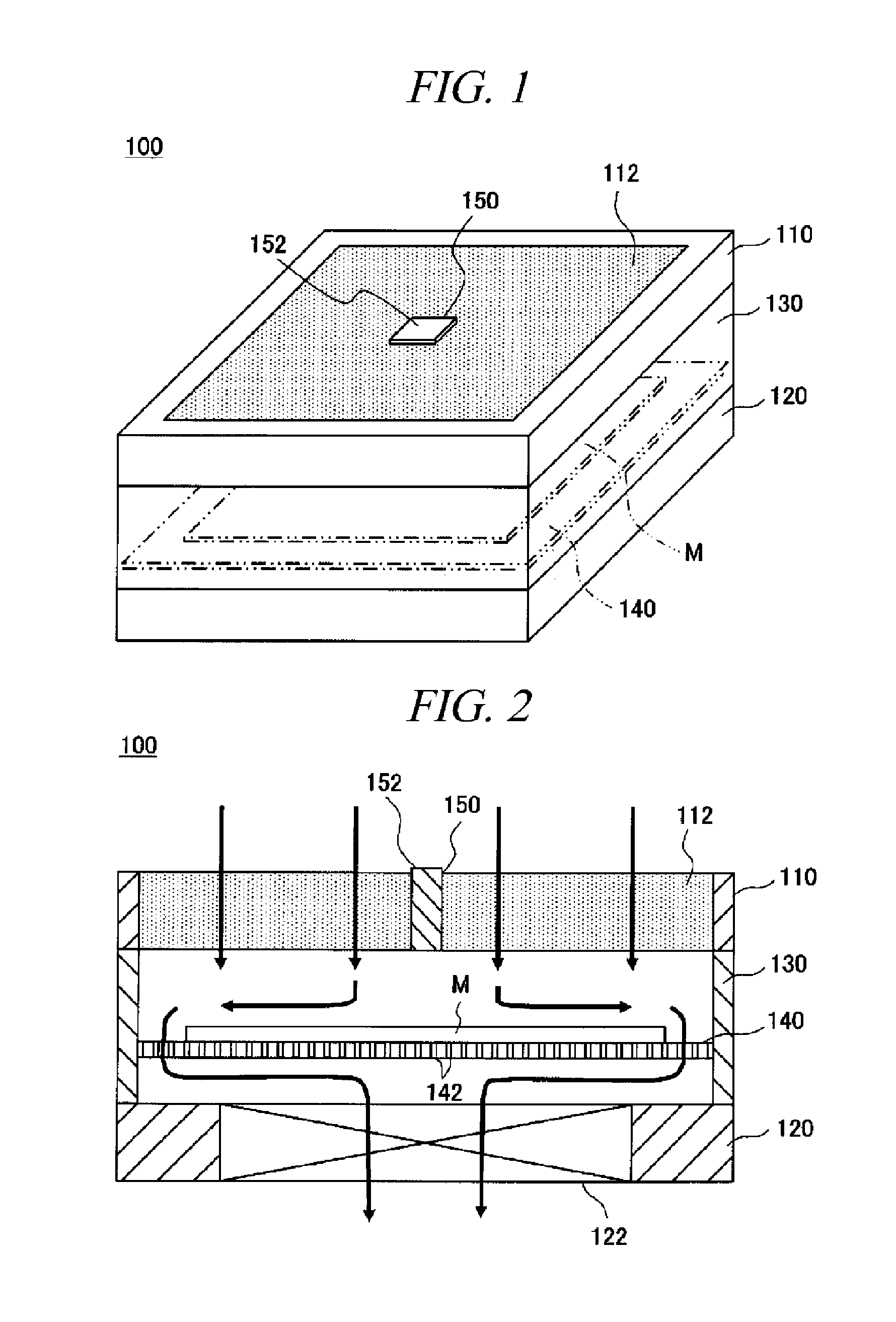
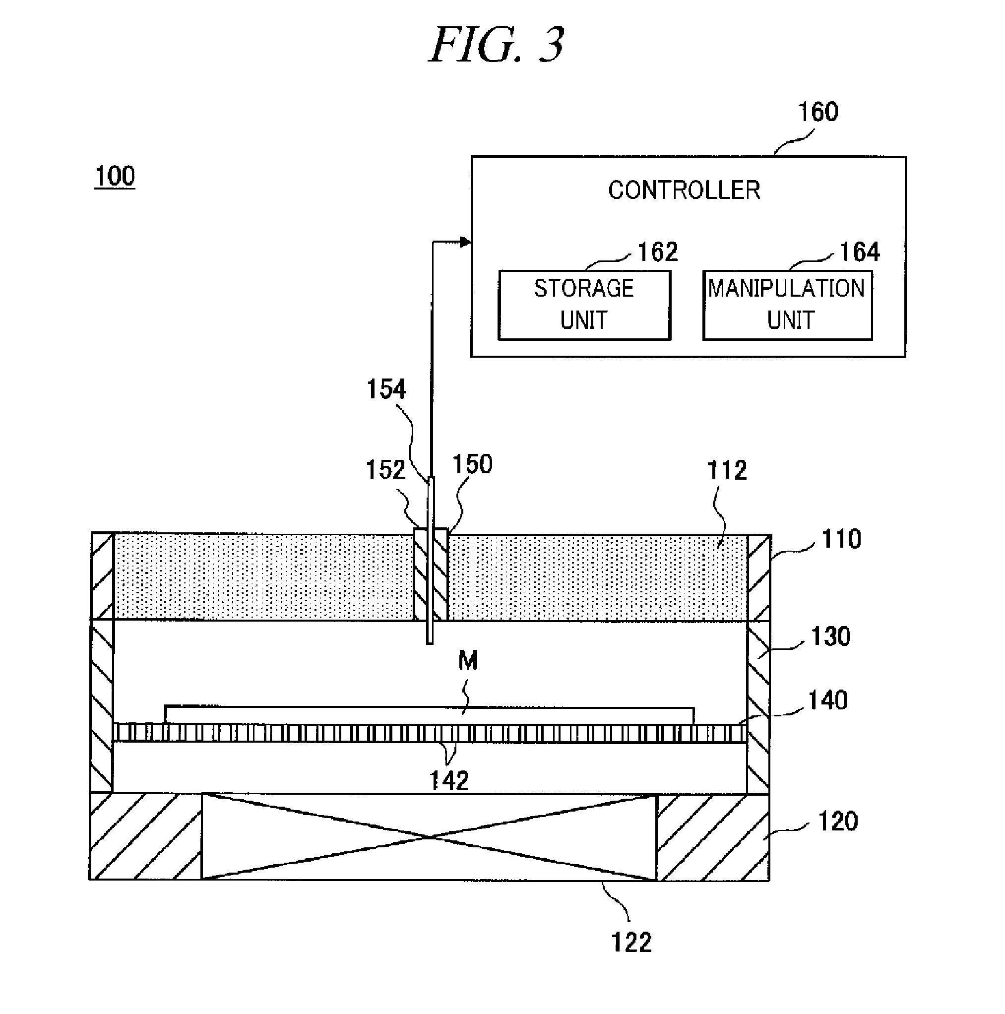
[0038]First, a substrate accommodation device in accordance with the illustrative embodiment will be described with reference to the accompanying drawings. Here, for example, the substrate accommodation device is configured to accommodate and transfer mask blanks as substrates one by one. FIG. 1 is a perspective view illustrating a configuration of the substrate accommodation device in accordance with the illustrative embodiment. FIG. 2 is a cross sectional view of the substrate accommodation device. As depicted in FIG. 1, the substrate accommodation device 100 has a box-shaped appearance and is configured to accomm...


PUM

PropertyMeasurementUnit
Temperatureaaaaaaaaaa
Threshold limitaaaaaaaaaa

Abstract

A substrate accommodation device can effectively prevent a foreign substance from adhering to a substrate accommodated therein depending on an environment where the substrate accommodation device is used. The substrate accommodation device 100 includes an air supply unit 110 configured to introduce exterior air into the substrate accommodation device 100; an exhaust unit 120 disposed to face the air supply unit 110; a substrate mounting plate 140 provided between the air supply unit 110 and the exhaust unit 120 and provided with holes 142 through which the air supply unit 110 and the exhaust unit 120 communicate with each other; an air supply filter 112 provided at the air supply unit 110; and a fan 122 provided at the air supply unit 110 or the exhaust unit 120. Further, one of a state sensor configured to detect a state within the substrate accommodation device 100, a particle charging device, and a temperature controller or a combination of two or more thereof is detachably provided in a mounting hole 150. (FIG. 2)

Description

TECHNICAL FIELD[0001]The present disclosure relates to a substrate accommodation device for accommodating and transferring a substrate such as a mask blank.BACKGROUND ART[0002]In order to form a fine circuit pattern on a semiconductor wafer or a FPD substrate, there has been known a lithography technology using a photomask. In this lithography technology, a substrate such as a semiconductor wafer having thereon a resist film is exposed to an electromagnetic wave outputted from an exposure light source through a photomask having a predetermined circuit pattern. As a result, the predetermined circuit pattern of the photomask is transferred and shrunk onto the semiconductor wafer.[0003]Such a photomask is manufactured by forming the fine circuit pattern through repeatedly performing various processes such as a film formation, a chemical mechanical polishing (CMP), and a cleaning on a surface of a substrate called a mask blank. The mask blank is prepared by forming a light blocking film...

Claims


Application Information

Patent Timeline
IPC IPC(8): F17D3/00B65D77/04B65D81/20B65D85/86G03F1/66H01L21/673
CPCH01L21/67393H01L21/67359Y10T137/86035B65D85/00G03F1/82H01L21/673
Inventor MORIYA, TSUYOSHI
Owner TOKYO ELECTRON LTD
Learn More