Image heating apparatus

Active Publication Date: 2013-05-30
CANON KK
View PDF6 Cites 10 Cited by
  • Summary
  • Abstract
  • Description
  • Claims
  • Application Information

AI Technical Summary

Benefits of technology

[0008]An object of the present invention is to, in an image heating apparatus provided with a rubbing member rubbing a heating rotating body, suppress nonuniformity of rubbing of a heating r

Problems solved by technology

The rubbing member uniformly rubs the heating rotating body, and therefore the fine scuffs concentra

Method used


Image

  • Image heating apparatus
  • Image heating apparatus
  • Image heating apparatus

Examples


Example

Example 1

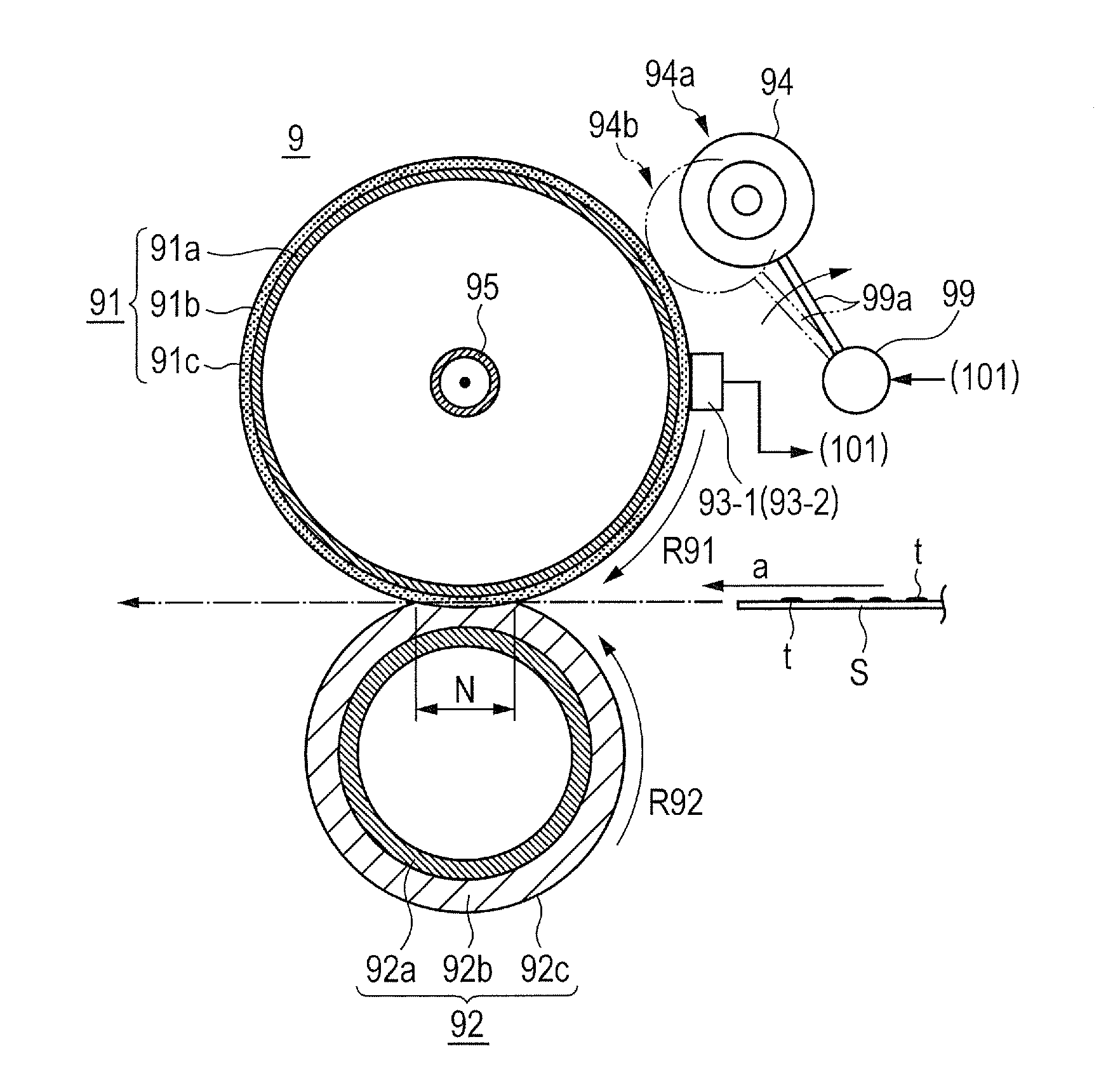
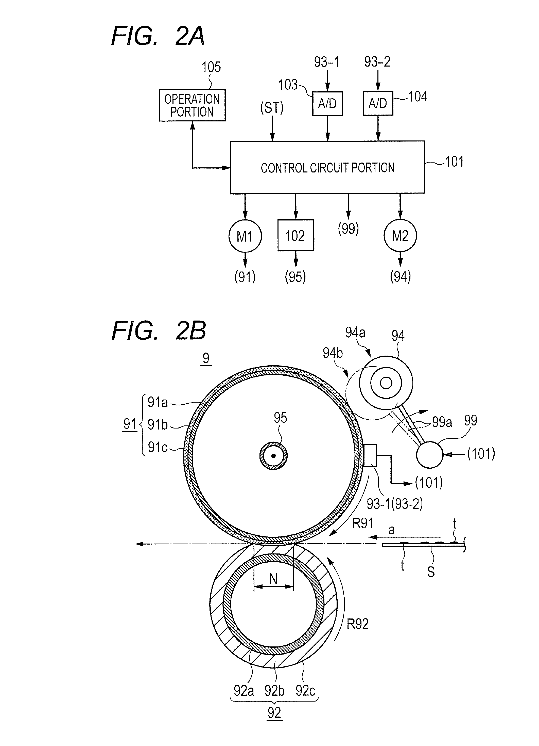
[0025]In this example, an image heating apparatus is provided as a fixing device for fixing an image, which is formed on a recording material with toner in an image forming apparatus using an electrophotographic system, onto the recording material.

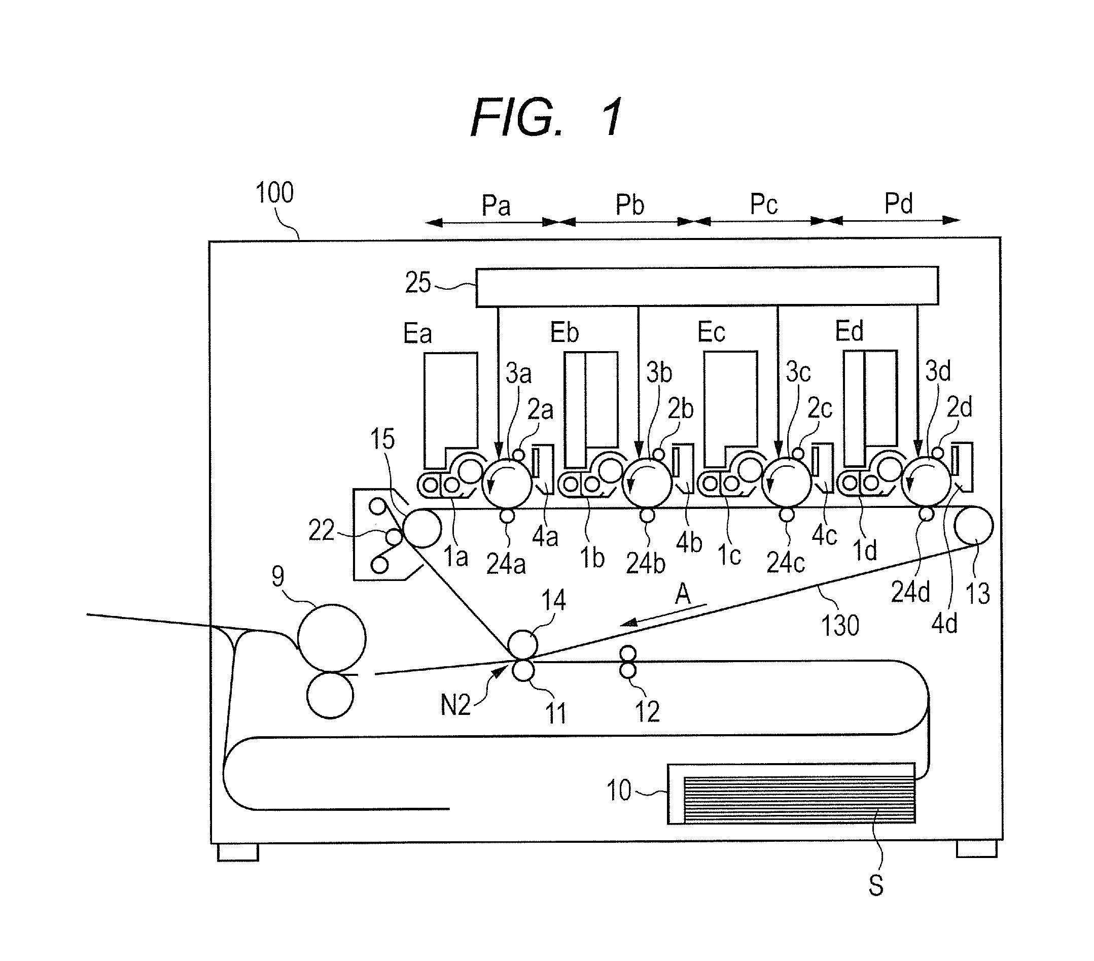
[0026]Image Forming Apparatus

[0027]FIG. 1 is a schematic cross-sectional configuration diagram illustrating one example of an image forming apparatus provided with a fixing device according to this embodiment. An image forming apparatus 100 of this embodiment is a full-color laser beam printer using an electrophotographic system. In the image forming apparatus, first, second, third, and fourth image forming portions Pa to Pd is provided in parallel. In the image forming portions Pa to Pd, toner images of different colors are formed through the processes of latent image formation, development, and transfer.

[0028]The image forming portions Pa to Pd are provided with drum type electrophotographic photosensitive members, that is, phot...

Example

Second Embodiment

[0102]The feature of this embodiment is to add a temperature uniforming member (heat homogenizing unit) to smooth a longitudinal temperature difference of a fixing roller. By executing the second embodiment, it is intended to reduce down time which is occurred when fixing operation is performed in the case that the recording materials having different sizes are stored. Hereinafter, the fixing device in this embodiment will be described. Description of the portions common to those in the first embodiment will be omitted.

[0103]FIG. 9 is a crosswise sectional schematic diagram of a main portion of a fixing device 9 in this embodiment. The fixing device 9 in FIG. 2B of the first embodiment is further provided with a heat homogenizing roller 96 as the temperature uniforming member in order to smooth a longitudinal temperature difference of a fixing roller 91. Other configurations of the fixing device are similar to the configurations of the fixing device of the first emb...

Example

[0108]In the first embodiment, when the homogenization treatment is performed after the continuous fixing operation for a large amount of the recording materials having a small longitudinal width, if the temperature difference of the longitudinal of the fixing roller 91 is large, the waiting time is required until the temperature difference goes down within a predetermined temperature difference (step S1 of FIG. 8).

[0109]Thus, in this embodiment, in order to reduce the waiting time, when it is determined that the longitudinal temperature difference of the fixing roller 91 is more than a predetermined value, the heat homogenizing roller 96 is shifted to the acting position 96b, and the temperature difference in the fixing roller is homogenized.

[0110]FIG. 10 is a flow chart showing a control flow in the homogenization treatment mode in this embodiment. When the homogenization treatment mode is started, in step S1, the control circuit portion 101 determines the temperature difference (...


PUM


Abstract

In an image heating apparatus in which a heating rotating body heats a recording material bearing an image and a rubbing member rubs the heating rotating body to eliminate gloss streaks, an image failure such as gloss unevenness does not occur in a normal plain paper and a coated paper, and a toner gloss on the coated paper can be enhanced. A longitudinal temperature difference of a heating rotating body 91 is controlled within a predetermined temperature, so that the surface of the heating rotating body can be uniformly roughed. Consequently, an image failure due to scuffs on the surface of the heating rotating body and gloss unevenness due to unevenness of roughness of the surface of the heating rotating body are prevented, and thus a good fixed image can be obtained.

Description

BACKGROUND OF THE INVENTION[0001]1. Field of the Invention[0002]The present invention relates to an image heating apparatus heating a toner image on a recording material, and more particularly to an image heating apparatus provided with a rubbing rotating body which rubs a heating rotating body heating the toner image on the recording material. The image heating apparatus is used in an image forming apparatus such as a copier, a printer, a facsimile machine, and a complex machine having the functions thereof.[0003]2. Description of the Related Art[0004]Conventionally, in an image forming apparatus utilizing an electrophotographic system or the like, a toner image formed on a recording material is pressurized and heated at a nip portion between a heating rotating body and a nip forming member. A material such as fluororesin having excellent releasing property is used for a surface of the heating rotating body.[0005]Among recording materials, there is a recording material having a pro...

Claims


Application Information

Patent Timeline
IPC IPC(8): G03G15/20
CPCG03G15/2042G03G15/2039
Inventor HASEGAWA, KAZUHIRO
Owner CANON KK
Why Eureka
Try Eureka