Plug connector, receptacle connector and electrical connector assembly

a technology of receptacle connectors and plug connectors, which is applied in the direction of coupling contact members, coupling device connections, electric discharge lamps, etc., can solve the problems of easy interference between traditional electrical terminals and connectors, easy deformation of electrical terminals, and easy failure to contact complementary terminals, etc., to achieve stable signal transmission

Inactive Publication Date: 2013-05-30
CHENG UEI PRECISION IND CO LTD
View PDF12 Cites 21 Cited by
  • Summary
  • Abstract
  • Description
  • Claims
  • Application Information

AI Technical Summary

Benefits of technology

[0006]For overcoming above defects, an object of the present invention is to provide a plug connector, a receptacle connector and an electrical connector assembly, which can form a stable connection to provide a stable signal transmission and are not easy to be effected by external shocks, wherein the combination of the receptacle terminal and the receptacle housing can not be affected by the pulling operation of the plug terminal of the plug connector.

Problems solved by technology

However, because of the configuration of the inclined hanging arm, the combination of the traditional electrical terminal and the connector is easy to be affected when the complementary connector is pulled out from the connector.
Namely, the electrical terminal is easy to escape from the connector or even be pulled out, so this will result in the deformation of the electrical terminal.
Moreover, the configuration of the traditional electrical terminal provides only one single position to contact with the complementary terminal, so that it is easy to fail to contact with the complementary terminal when the connector suffers from the factors of the external shocks and the like.
That will result in the problems of unstable signal transmission or even signal interruption and so on.
These problems are especially easy to occur in a board-to-board connector having multiple electrical terminals
But the hard interference fit cannot provide a stable contact and is easily loosened to result in the bad electrical transmission when the connector is slightly pulled by the external shocks.

Method used


Image

  • Plug connector, receptacle connector and electrical connector assembly
  • Plug connector, receptacle connector and electrical connector assembly
  • Plug connector, receptacle connector and electrical connector assembly

Examples


Embodiment Construction

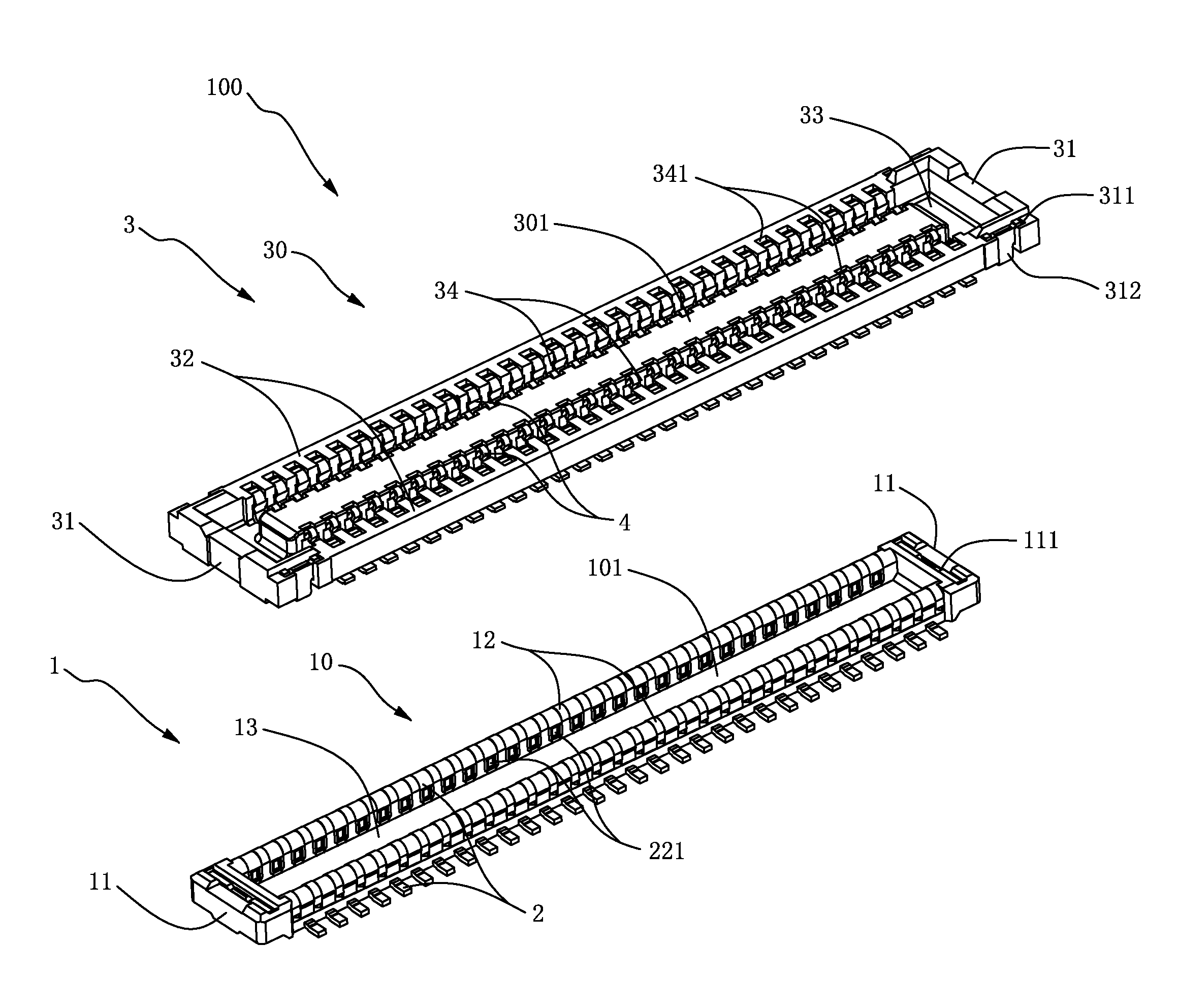
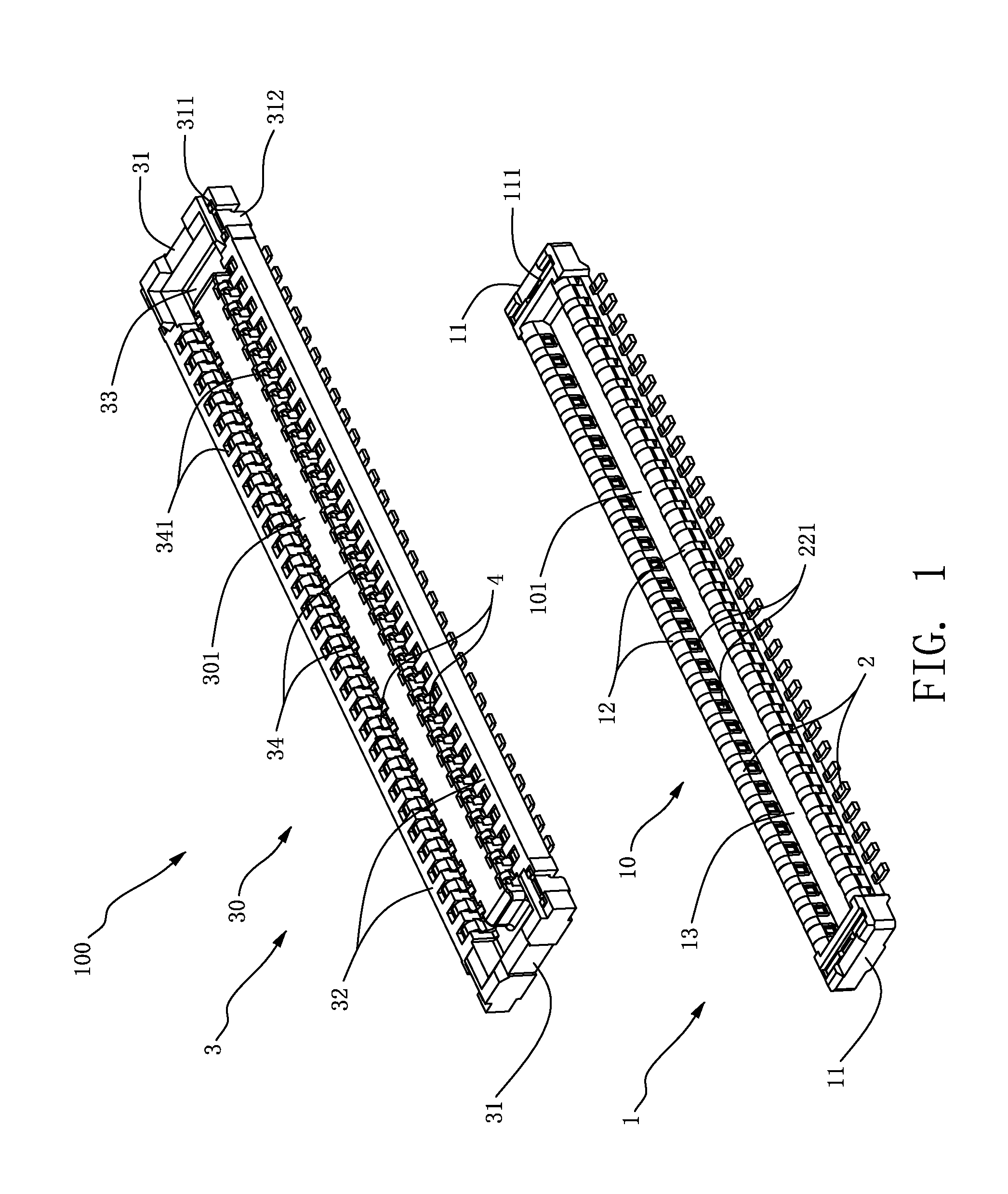
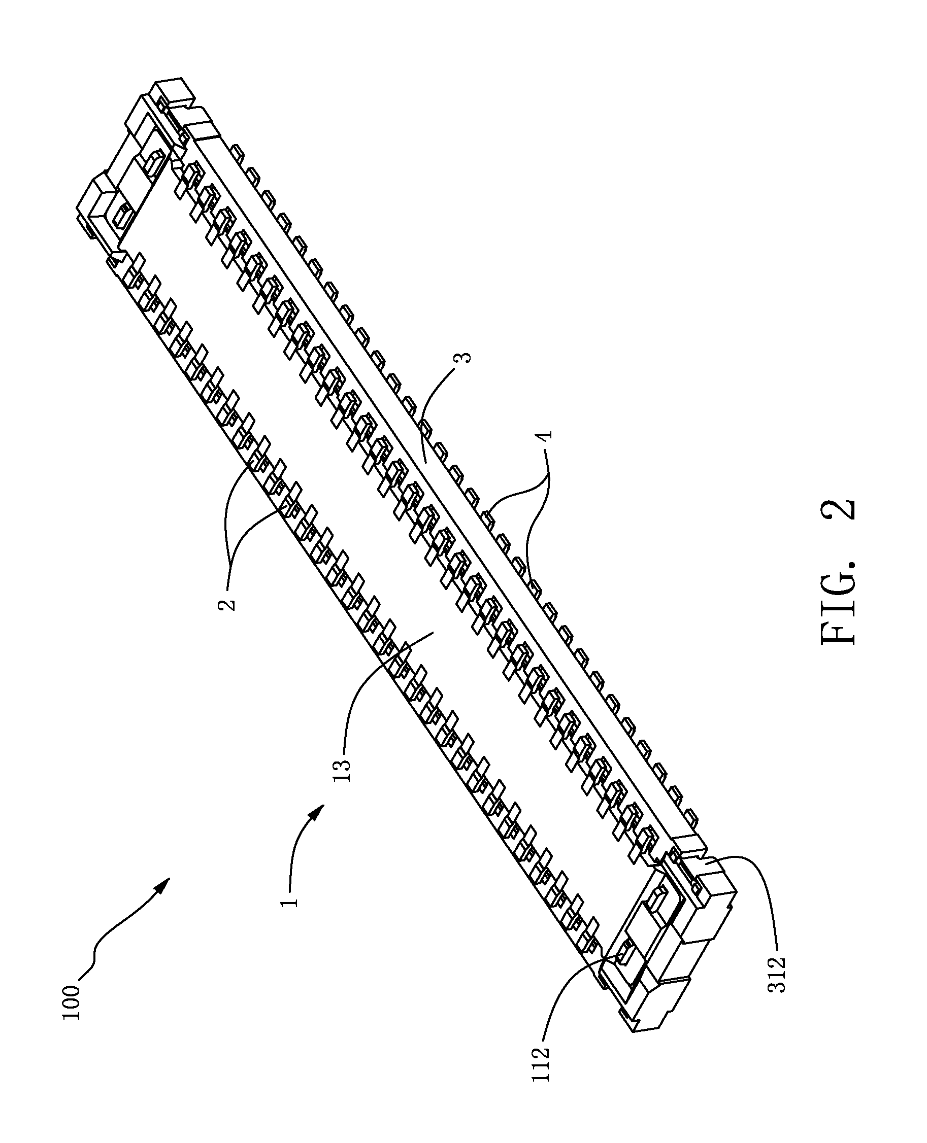
[0016]Please refer to FIGS. 1 to 6, which are one preferred embodiment of an electrical connector assembly 100 of the present invention, the electrical connector assembly 100 of the present invention comprises a plug connector 1 and a receptacle connector 3 mated with each other.

[0017]Please refer to FIGS. 1 to 4, the receptacle connector 3 of the electrical connector assembly 100 of the present invention has a flat rectangular shape and comprises a receptacle housing 30 being made of insulating material. The receptacle housing 30 has two opposite end walls 31, two opposite sidewalls 32 being perpendicular to and respectively connected to the two end walls 31, a bottom plate 33 connecting the bottoms of the two end walls 31 and the two sidewalls 32, and a protruding plate 301 standing on the bottom plate 33, being located between the two sidewalls 32 and being parallel to the two sidewalls 32. Two opposite ends of the protruding plate 301 and the two sidewalls 11 are respectively sp...


PUM


Abstract

A plug connector, a receptacle connector and an electrical connector assembly are provided. The receptacle connector includes a receptacle housing and a plurality of receptacle terminals. Each receptacle terminal includes a first and a second wing portions, and a first and a second edge portions. The receptacle housing disposes shoulders respectively corresponding to the first and the second wing portions. The plug connector includes a plug housing and a plurality of plug terminal. Each plug terminal includes a first and a second contact portions. When the plug connector and the receptacle connector are mated together, the plug terminal and the receptacle terminal can realize a two-position contact for providing a stable signal transmission. When pulling out the plug connector, the shoulders of the receptacle housing can block the receptacle terminal to be pulled out thereby ensuring the stable combination of the receptacle terminal and the receptacle housing.

Description

BACKGROUND OF THE INVENTION[0001]1. Field of the Invention[0002]The present invention relates to a plug connector, a receptacle connector and an electrical connector assembly, and more particularly to a plug connector and a receptacle connector being mated together and to an electrical connector assembly having improved components, being capable of providing a stable combination and forming an electrical connection between two circuit boards.[0003]2. Description of the Prior Art[0004]At present, a connector mainly includes a housing and a plurality of electrical terminals. The connector is mounted on a circuit board for being mated with a complementary connector. By the terminals of the two connectors contacting with each other, the two connectors form an electrical transmission therebetween. Therefore, the configuration of the electrical terminal is one of the main factors of whether the electrical terminal can provide a stable contact. In view of this, the electrical terminal of t...

Claims


Application Information

Patent Timeline
Patent Type & Authority Applications(United States)
IPC IPC(8): H01R24/28
CPCH01R12/716H01R24/60H01R13/11H01R12/73H01R13/20
Inventor HUANG, SHENG-YUANYU, SHENG-NANCHIANG, CHIH-HSIEN
Owner CHENG UEI PRECISION IND CO LTD
Why Eureka
Try Eureka