Coaxial connector

a technology of coaxial connectors and coaxial connectors, which is applied in the direction of coupling devices, two-part coupling devices, electrical apparatus, etc., can solve the problems of reducing the production rate of coaxial connectors, affecting the stability of coaxial connectors, so as to improve signal transmission stability and efficiency, excellent electrical connections

Active Publication Date: 2010-12-02
ADVANCED CONNECTEK INC
View PDF6 Cites 13 Cited by
  • Summary
  • Abstract
  • Description
  • Claims
  • Application Information

AI Technical Summary

Benefits of technology

[0007]The main objective of the invention is to provide a coaxial connector that is manufactured without soldering yet provides excellent electrical connection between the coaxial connector and a coaxial cable mounted thereon to improve signal transmission stability and efficiency.
[0008]A coaxial connector in accordance with the present invention has a metal shell, an insulative housing and a terminal. The metal shell has a body, a cavity defined in the body and a clamping cover formed on the body. The insulative housing is mounted in the cavity and has a base, a chamber defined in the base and a wire-pressing member being resilient and formed on the base. The terminal is mounted in the chamber and has a plate aligned with the wire-pressing member and two contacting arms protruding from the plate. When a coaxial cable is connected to the coaxial connector, the wire-pressing member is bent to precisely position a core wire of the coaxial cable on the plate and stabilize signal transmission between the coaxial connector and a coaxial cable.

Problems solved by technology

However, the core wire and the terminal are soldered together manually through a magnifier so manufacturing the coaxial connector is labor and time intensive and production rate of the coaxial connector is reduced.
However, the pressing member is not resilient and easily snaps or inadvertently moves after bending.
Therefore, the pressing member cannot precisely press against the core wire so that the core wire does not maintain contact with the terminal, so lowering signal transmission stability or causing signal transmission failure.

Method used


Image

  • Coaxial connector
  • Coaxial connector
  • Coaxial connector

Examples


Embodiment Construction

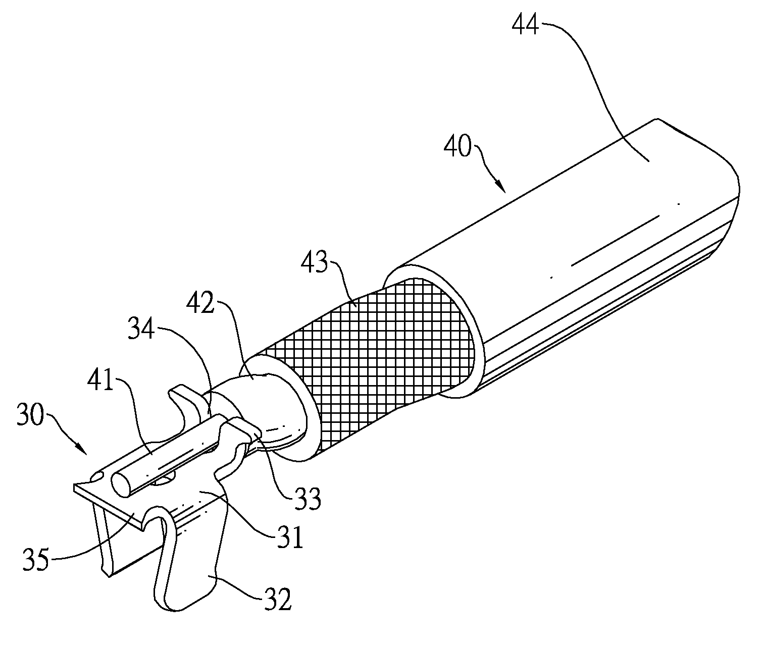
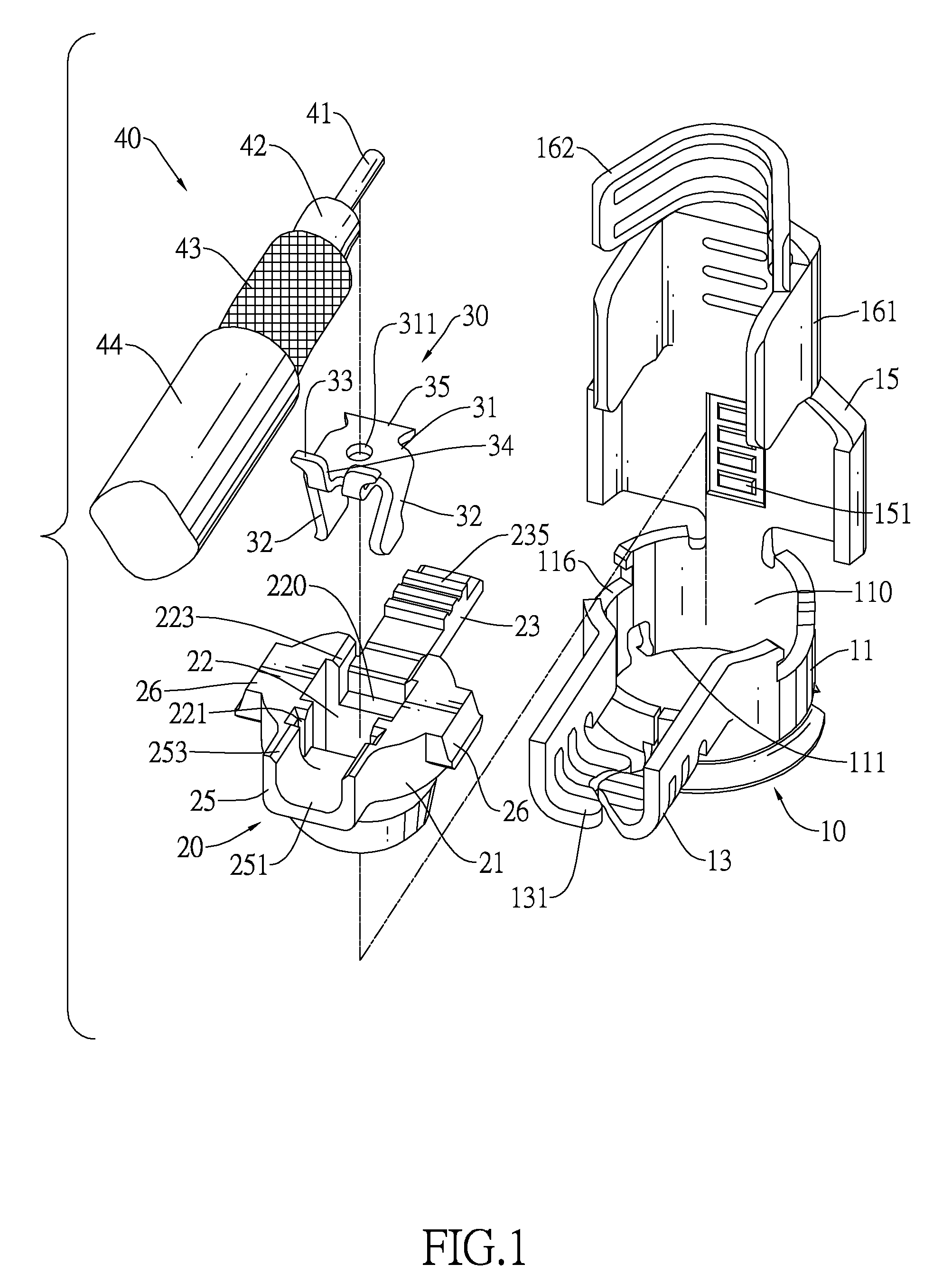
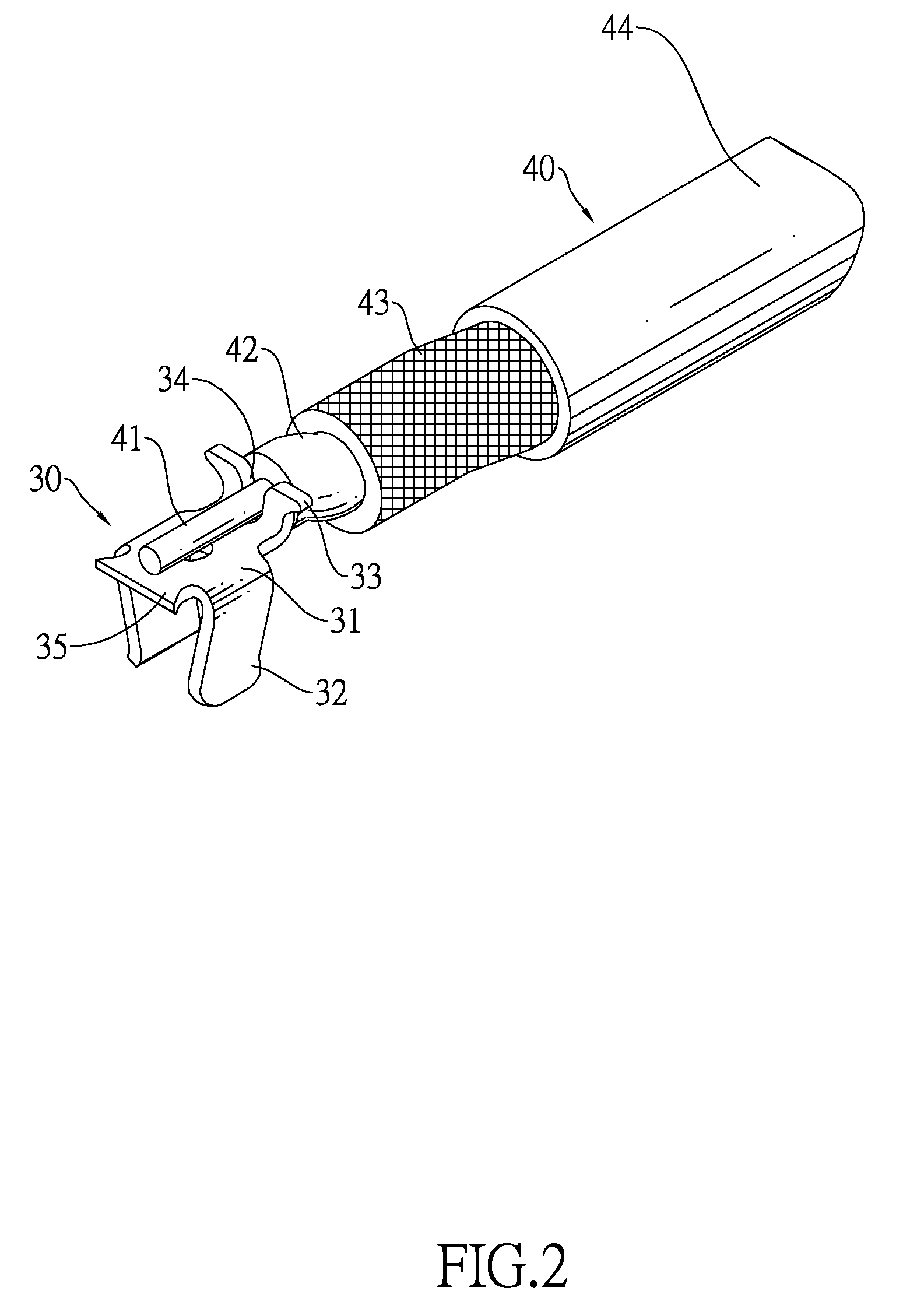
[0017]With reference to FIGS. 1 to 3, a coaxial connector in accordance with the present invention is connected to a coaxial cable (40). The coaxial cable (40) has a core wire (41), an inner insulator (42), a mesh shield (43) and an insulative jacket (44) sequentially formed from a center to an outside of the coaxial cable (40).

[0018]The coaxial connector in accordance with the present invention comprises a metal shield (10), an insulative housing (20) and a terminal (30).

[0019]The metal shell (10) has a body (11), a mounting bracket (13) and a clamping cover (15).

[0020]The body (11) has a cavity (110) and may further have two opposite positioning recesses (116). The cavity (110) is defined through the body (11) and has a socket opening (111) to accommodate a corresponding coaxial plug connector. The positioning recesses (116) are defined in body (11).

[0021]The mounting bracket (13) is formed on and protrudes outwards from the body (11) and has a cable slot (131) defined in the moun...


PUM


Abstract

A coaxial connector has a metal shell, an insulative housing and a terminal. The metal shell has a body, a cavity defined in the body and a clamping cover formed on the body. The insulative housing is mounted in the cavity and has a base, a chamber defined in the base and a wire-pressing member being resilient and formed on the base. The terminal is mounted in the chamber and has a plate aligned with the wire-pressing member and two contacting arms protruding from the plate. When a coaxial cable is connected to the coaxial connector, the wire-pressing member is bent to precisely position a core wire of the coaxial cable on the plate and stabilize signal transmission between the coaxial connector and a coaxial cable.

Description

BACKGROUND OF THE INVENTION[0001]1. Field of the Invention[0002]The present invention relates to a connector, and more particularly to a coaxial connector that is manufactured without soldering yet provides excellent electrical connection between the coaxial connector and a coaxial cable mounted thereon to improve signal transmission stability and efficiency.[0003]2. Description of Related Art[0004]A conventional coaxial connector is mounted on a coaxial cable and has a metal shell, an insulative housing and a terminal. The metal shell is L-shaped 11 and has a cavity and a clamping cover. The insulative housing is mounted in the cavity. The terminal is mounted in the insulative housing and has a solder cup soldered on a core wire of the coaxial cable. After the insulative housing and terminal are mounted into the metal shell, the clamping cover is bent down to cover the cavity with the core wire mounted securely in the metal shell. However, the core wire and the terminal are soldere...

Claims


Application Information

Patent Timeline
Patent Type & Authority Applications(United States)
IPC IPC(8): H01R9/05H01R24/38
CPCH01R13/112H01R24/54H01R2103/00H01R9/0524H01R13/502
Inventor LEE, KUO-CHINGGUO, JIAN-GUANGWANG, YU-LONG
Owner ADVANCED CONNECTEK INC
Why Eureka
Try Eureka