Electric connector and insertion method using the same

A technology for electrical connectors and socket connectors, which is applied to parts of connecting devices, devices to prevent wrong connections, and directions of connection, etc. The effect of stable signal transmission and stable docking

Active Publication Date: 2008-12-03
DEYI PRECISION ELECTRONIC IND CO LTD PANYU
View PDF0 Cites 13 Cited by
  • Summary
  • Abstract
  • Description
  • Claims
  • Application Information

AI Technical Summary

Problems solved by technology

However, when the memory card 4 is inserted, each first contact point 450 of the first interface 45 will first contact the front contact portion 123 of each conductive terminal 120 correspondingly, and only then contact the rear contact portion of each conductive terminal 120 after being inserted in place. 124 is stably connected. Therefore, during the insertion process of the memory card 4, there will be a short-term conduction, and then there will be a short-term non-conduction, and then a stable electrical conduction will be produced. In this way, it may cause damage to the system and the memory card. damage; and because there may be more than one interface on the surface of the memory card 4, after the memory card 4 is inserted in place, the front contact portion 123 of the conductive terminal 120 may also be contacted with other interfaces on the surface of the memory card 4 (such as the second interface 46 The second contact point 460) of the memory card 4 is in contact with each other. Because the signals transmitted or the voltages carried by the various interfaces of the memory card 4 are different, there will be an unspecified conduction, which will cause confusion in signal transmission, and then cause damage to the system and the memory card.

Method used


Image

  • Electric connector and insertion method using the same
  • Electric connector and insertion method using the same
  • Electric connector and insertion method using the same

Examples


Embodiment Construction

[0029] The electrical connector of the present invention will be further described below in conjunction with the accompanying drawings and specific embodiments.

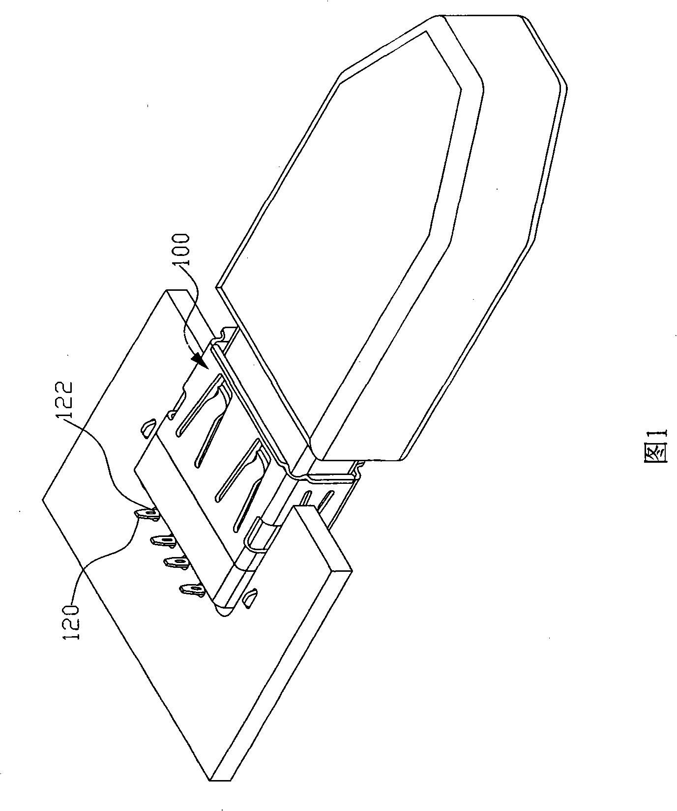
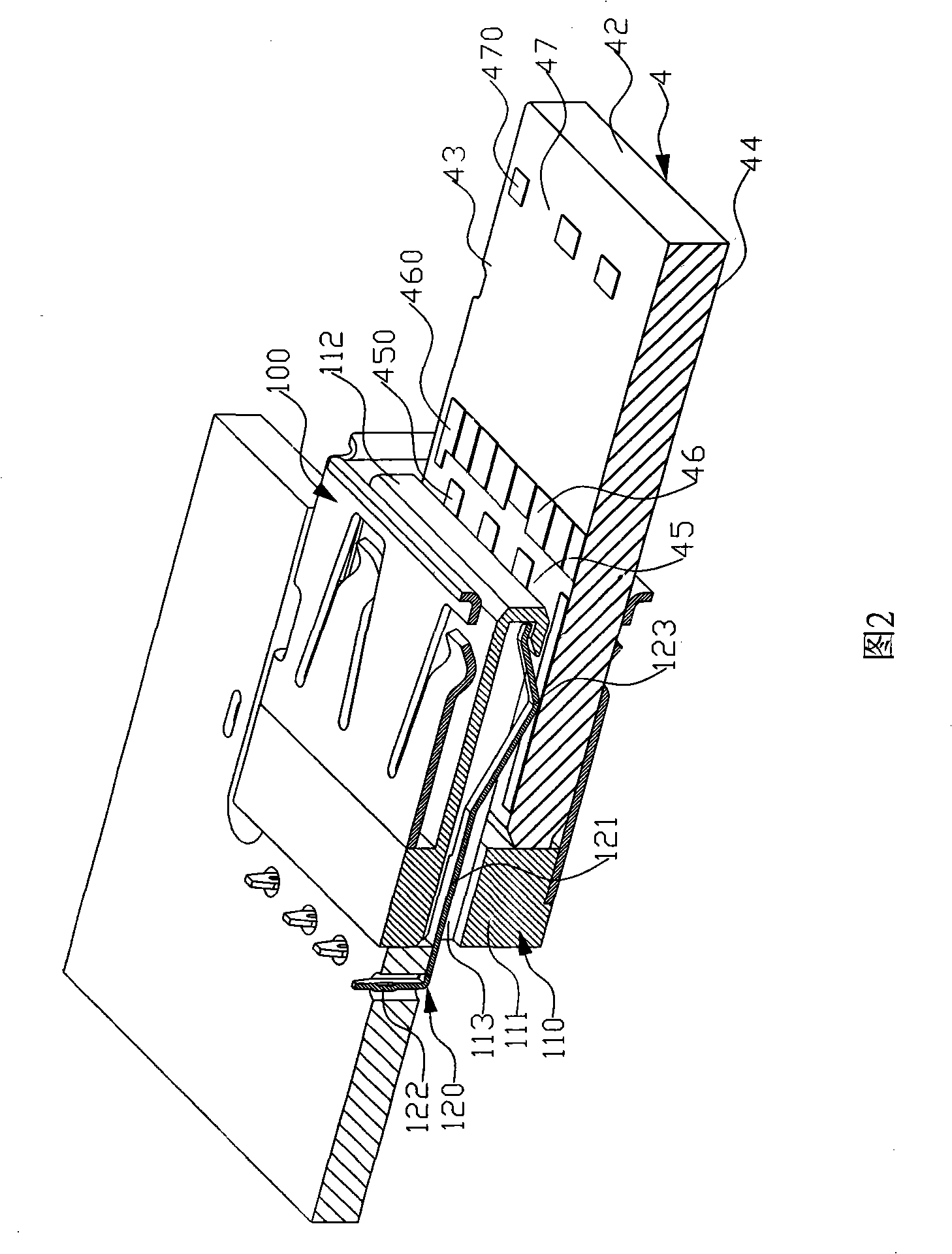
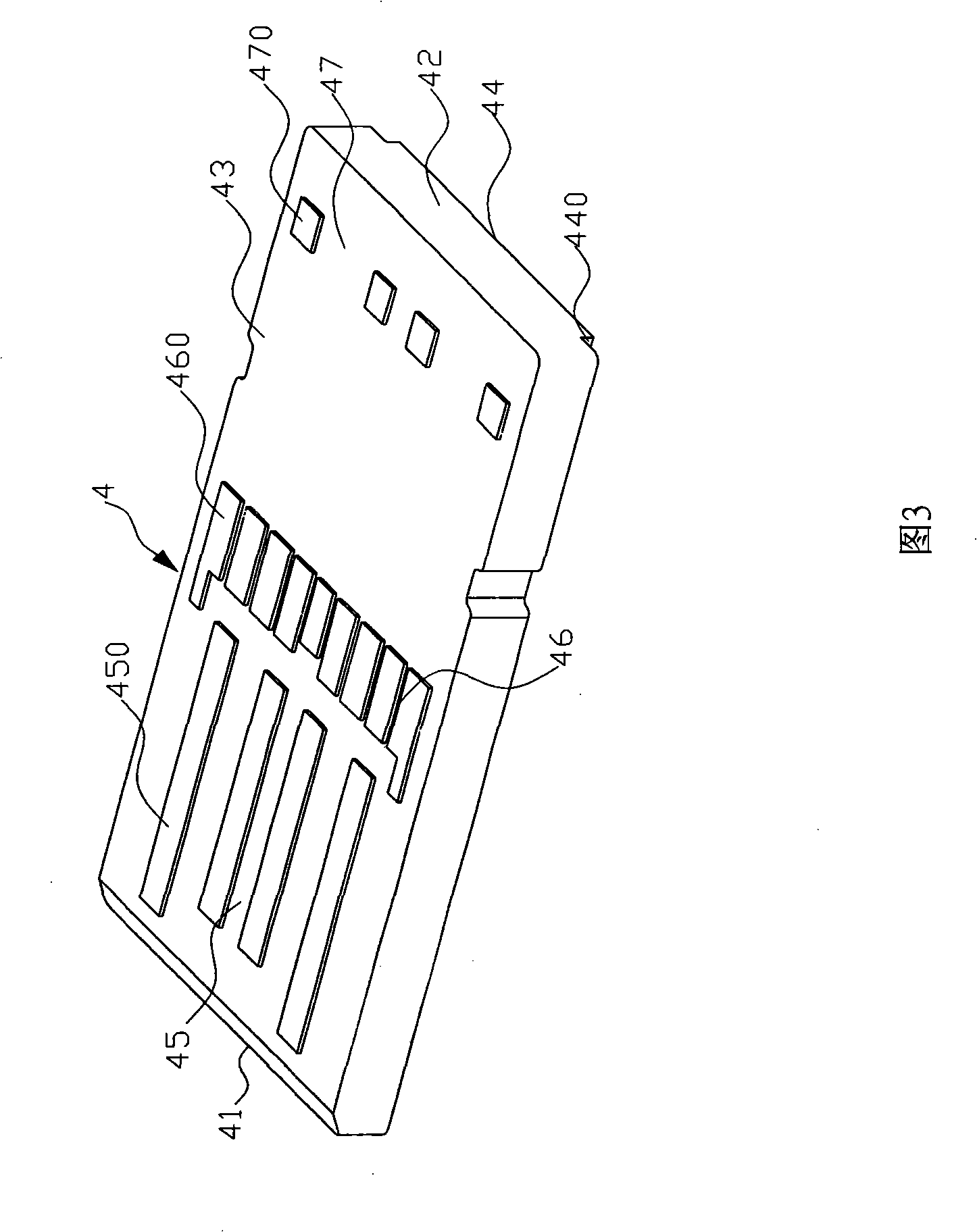
[0030] Please refer to Fig. 5, Fig. 7 and Fig. 12, the electrical connector 1 of the present invention can be installed on the circuit board 2, is used for docking a socket element (such as, standard USB socket connector) 3 or a plug element (such as , memory card Micard) 4, the electrical connector 1 includes an insulating body 5, a plurality of conductive terminals 6 and a shielding shell 7.

[0031] Please refer to Figures 5-8, the insulating body 5 includes a main body part 51, the front end of the main body part 51 faces the rear end surface and is recessed to form a first receiving space (inserting space) 52, the top of the main body part 51 and the second A plurality of first terminal channels 521 arranged at intervals extend between the top surfaces of the receiving space 52 . At least one side of the first ...


PUM


Abstract

The invention provides an electric connector, comprising an insulation body which is provided with a main body part; the front end of the main body part is concave towards the rear end so as to form a first receiving space; a plurality of first terminal passages which are intermittently arranged by the mainbody part extend from the top surface of the first receiving space; the front end of the main body part is provided with a second receiving space which is communicated with the first receiving space; the front end of the main body part extends forwards to form a hyoplastron; the second receiving space is arranged above the hyoplastron; the hyoplastron is provided with a working surface; a plurality of second terminal passages which are intermittently arranged extend on the working surface; the electric connector also comprises a plurality of first conductive terminals which are respectively received in the first terminal passage correspondingly and a plurality of second conductive terminals which are respectively received inside the second terminal passage correspondingly. When a memory card is inserted, the crosstalk of other signals does not occur; the signal transmission is stable; furthermore, after the memory card is inserted in place, the convex quantity is not too long, the shaking does not occur, and the butting is firm.

Description

【Technical field】 [0001] The present invention mainly relates to an electrical connector, especially an electrical connector that can be connected to a socket component (such as a standard USB socket connector) and can be stably connected to a plug component (such as a memory card), and the Insertion method of electrical connector. 【Background technique】 [0002] USB (Universal Serial Bus, Universal Serial Bus) is an electrical connector capable of transmitting high-speed signals, and is currently widely used to connect various electronic hosts and external devices. With the popularity of USB connectors, people in the industry began to conduct further research and development based on the original USB standard, designing various types of connectors with expansion functions that can simultaneously transmit standard USB interface electrical signals and additional electrical signals (such as memory card electrical signals) electrical connector. [0003] A standard USB connect...

Claims


Application Information

Patent Timeline
Patent Type & Authority Applications(China)
IPC IPC(8): H01R12/16H01R12/22H01R13/42H01R13/648H01R13/64H01R13/629H01R12/71
Inventor 陈裕升
Owner DEYI PRECISION ELECTRONIC IND CO LTD PANYU
Why Eureka
Try Eureka