Power-Sensing Circuit for Wireless Zone Sensors

a wireless zone and sensor technology, applied in the direction of lighting and heating equipment, instruments, heating types, etc., can solve the problems of not being able to properly control the temperature of various rooms in the dwelling, such as the kitchen, upper bedrooms, etc., to achieve a comfortable temperature for the occupants

Active Publication Date: 2013-06-06
TRANE INT INC
View PDF12 Cites 49 Cited by
  • Summary
  • Abstract
  • Description
  • Claims
  • Application Information

AI Technical Summary

Benefits of technology

[0004]In an embodiment, a heating, ventilating, and air conditioning (HVAC) system is provided for controlling climate conditions in a dwelling including a plurality of zones. The system includes a plurality of wireless thermostats disposed throughout the zones within the dwelling. Each thermostat is operable to control a climate condition in a corresponding zone by communicating signals through a network to a master control unit in communication therewith. The master control unit is operatively connected to a primary power source. The primary power source is operable to supply power to thermostats connected thereto, wherein thermostats powered by the primary power source operate in a high-powered mode. Each thermostat includes a secondary power source for supplying power when to operate in a low-power mode if a corresponding thermostat is not powered by the primary power source. Each thermostat operating in the high-power mode is configured to operate as a repeater operable to receive and route signals communicated through a wireless portion of the network.

Problems solved by technology

However, various rooms throughout the dwelling, such as the kitchen, upper bedrooms in multi-story homes, or rooms in which a more appreciable heating or cooling load is occurring may not be properly controlled to produce a comfortable temperature for the occupants.
While zoned systems have several known advantages, the overall cost installing and implementing such systems in a suitable infrastructure can be relatively expensive.

Method used


Image

  • Power-Sensing Circuit for Wireless Zone Sensors
  • Power-Sensing Circuit for Wireless Zone Sensors
  • Power-Sensing Circuit for Wireless Zone Sensors

Examples


Embodiment Construction

[0014]It should be understood at the outset that although an illustrative implementation of one or more embodiments are provided below, the disclosed systems and / or methods may be implemented using any number of techniques, whether currently known or in existence. The disclosure should in no way be limited to the illustrative implementations, drawings, and techniques illustrated below, including the exemplary designs and implementations illustrated and described herein, but may be modified within the scope of the appended claims along with their full scope of equivalents.

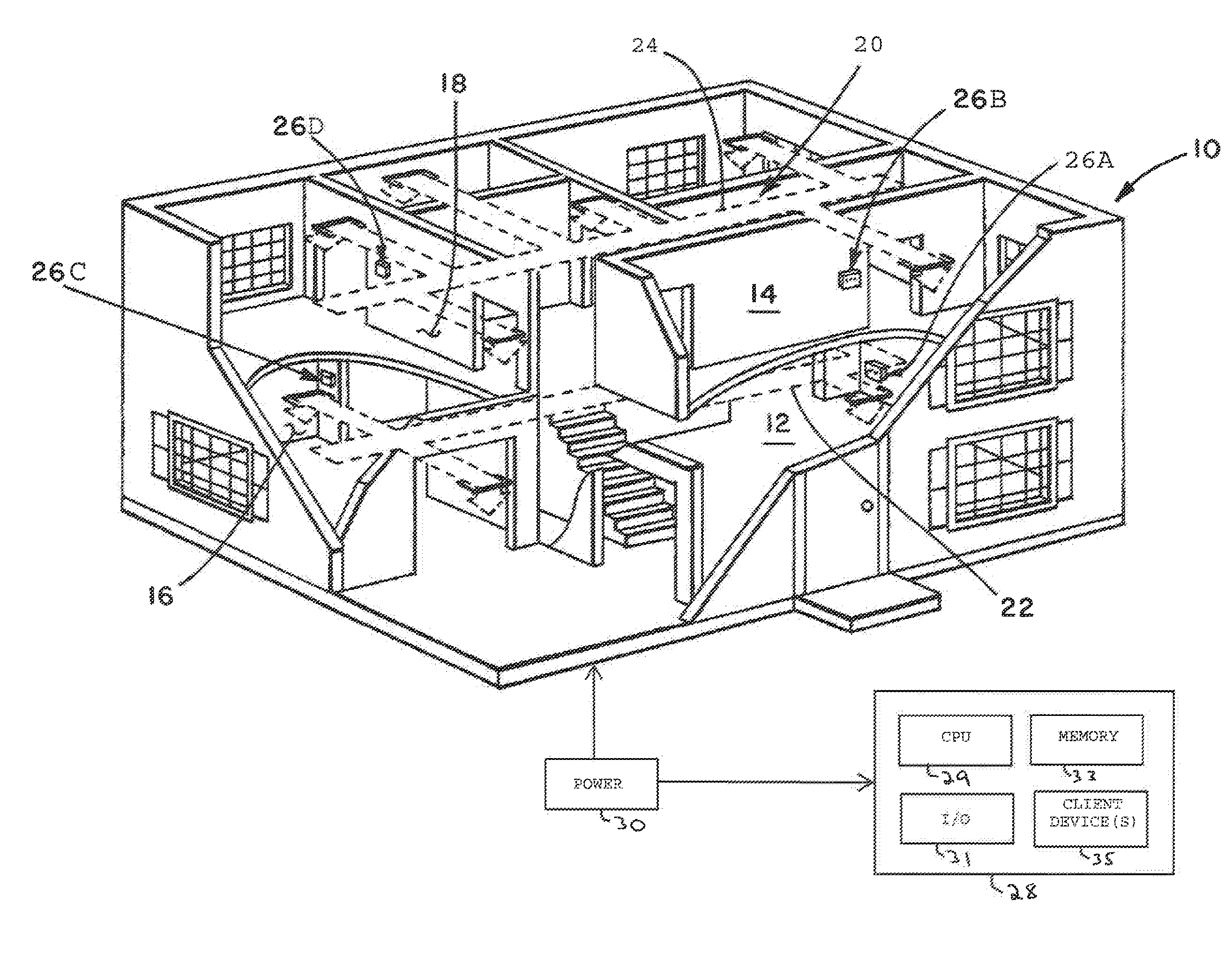
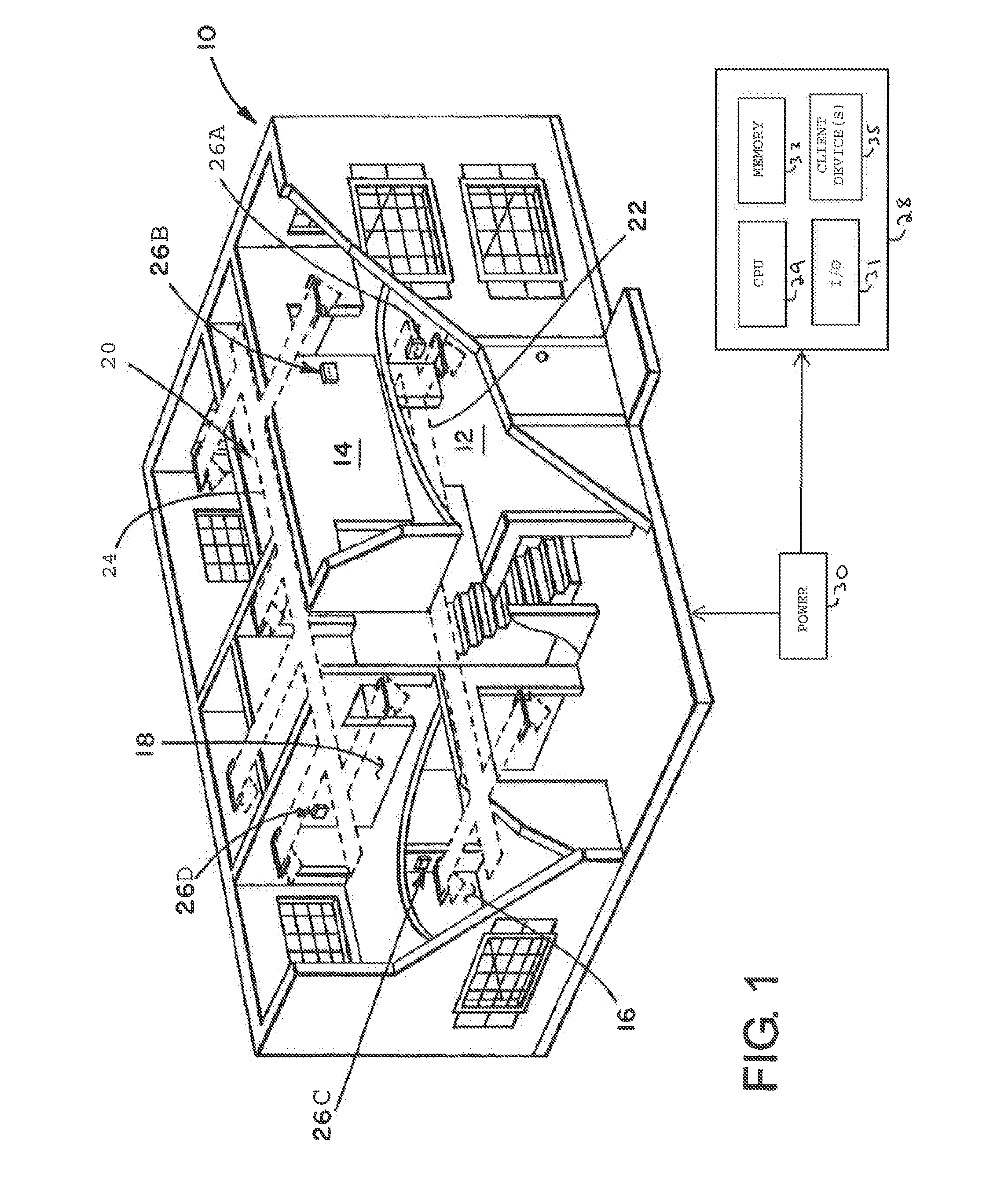
[0015]Disclosed herein are embodiments of an HVAC system and method for controlling climate conditions using a plurality of wireless thermostats disposed throughout various portions of a multi-zone enclosure. In accordance with an embodiment of the present disclosure, the plurality of thermostats communicatively link to a master control unit operable to effect control of the HVAC system in response to receiving cont...


PUM


Abstract

A system and method for controlling a heating, ventilating, and air conditioning (HVAC) system in a dwelling is provided. The system includes a plurality of wireless thermostats disposed throughout multiple zones within the dwelling and operable to control climate conditions in the corresponding zones. The system further includes a primary power source operable to supply power to thermostats for operating in a high-power mode when operatively connected thereto. The thermostats each include a secondary power source operable to supply power to the thermostats for operating in a low-power mode when the corresponding thermostat is not powered by the primary power source. Thermostats operating in the high-powered mode and are operable to receive and repeat signals originating from one or more thermostats operating in the low-power mode.

Description

BACKGROUND[0001]Conventional air conditioning systems, often referred to as heating, ventilating and air conditioning (HVAC) systems for residential dwellings and other installations typically utilize one thermostat for controlling the temperature in the entire controlled space. For example, in a residential dwelling the thermostat is normally located centrally, such as in an interior hallway. However, various rooms throughout the dwelling, such as the kitchen, upper bedrooms in multi-story homes, or rooms in which a more appreciable heating or cooling load is occurring may not be properly controlled to produce a comfortable temperature for the occupants.[0002]It is desirable to be able to control the temperature in various rooms or “zones” within a residential dwelling or other enclosed space. It is also desirable to be able to control the temperature at a particular area or in a particular room in a controlled interior space, and to control the HVAC system to provide an average te...

Claims


Application Information

Patent Timeline
Patent Type & Authority Applications(United States)
IPC IPC(8): F24F11/00G05D23/19F24F3/00
CPCF24F11/006G05D23/1934F24F2011/0068F24F2011/0067F24F11/30F24F11/62F24F11/54F24F11/56F24F11/58F24F11/46F24F11/66F24F11/52
Inventor STORM, TIMOTHY WAYNEMITCHELL, DANIEL J.
Owner TRANE INT INC
Why Eureka
Try Eureka