Solid state bilge pump switch

a bilge pump and solid-state technology, applied in the direction of positive-displacement liquid engines, machines/engines, relays, etc., can solve the problems of relatively short life of mechanical switches, sinking or damage to boats, and not being completely successful or relatively expensive solutions

Active Publication Date: 2013-06-06
LAKE RED ROCK
View PDF4 Cites 6 Cited by
  • Summary
  • Abstract
  • Description
  • Claims
  • Application Information

AI Technical Summary

Benefits of technology

[0011]From the foregoing disclosure and the following more detailed description of various preferred embodiments it will be apparent to those skilled in the art that the present invention provides a significant advance in the technology and art of bilge pump switches.

Problems solved by technology

However, bilge debris and other contamination built up over time and/or caused corrosion to prevent the mechanical components from moving as intended.
Additionally, these mechanical switches had relatively short lives compared to the boats in which they were installed and required replacement.
These electronic switches are susceptible to false alarms, which can b “burn up” the pump motor, and

Method used


Image

  • Solid state bilge pump switch
  • Solid state bilge pump switch
  • Solid state bilge pump switch

Examples


Embodiment Construction

[0022]It will be apparent to those skilled in the art, that is, to those who have knowledge or experience in this area of technology, that many uses and design variations are possible for the improved bilge pump switches disclosed herein. The following detailed discussion of various alternative and preferred embodiments will illustrate the general principles of the invention. Other embodiments suitable for other applications will be apparent to those skilled in the art given the benefit of this disclosure.

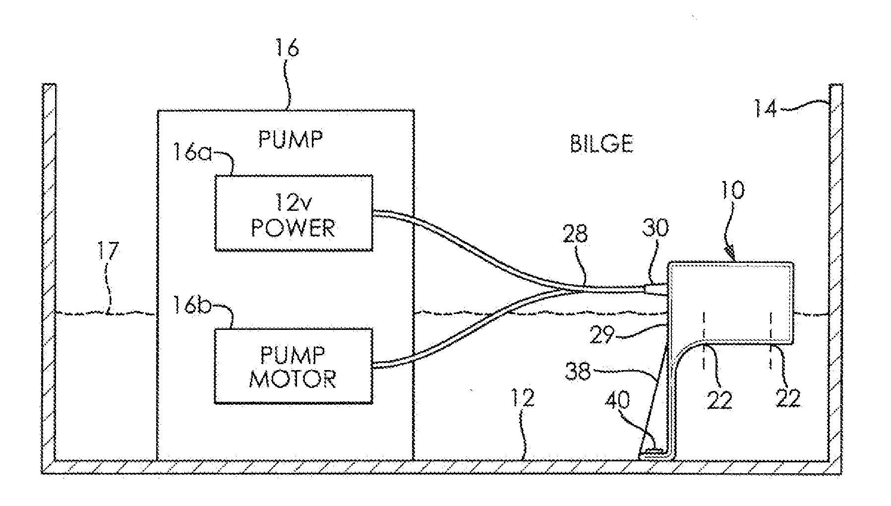
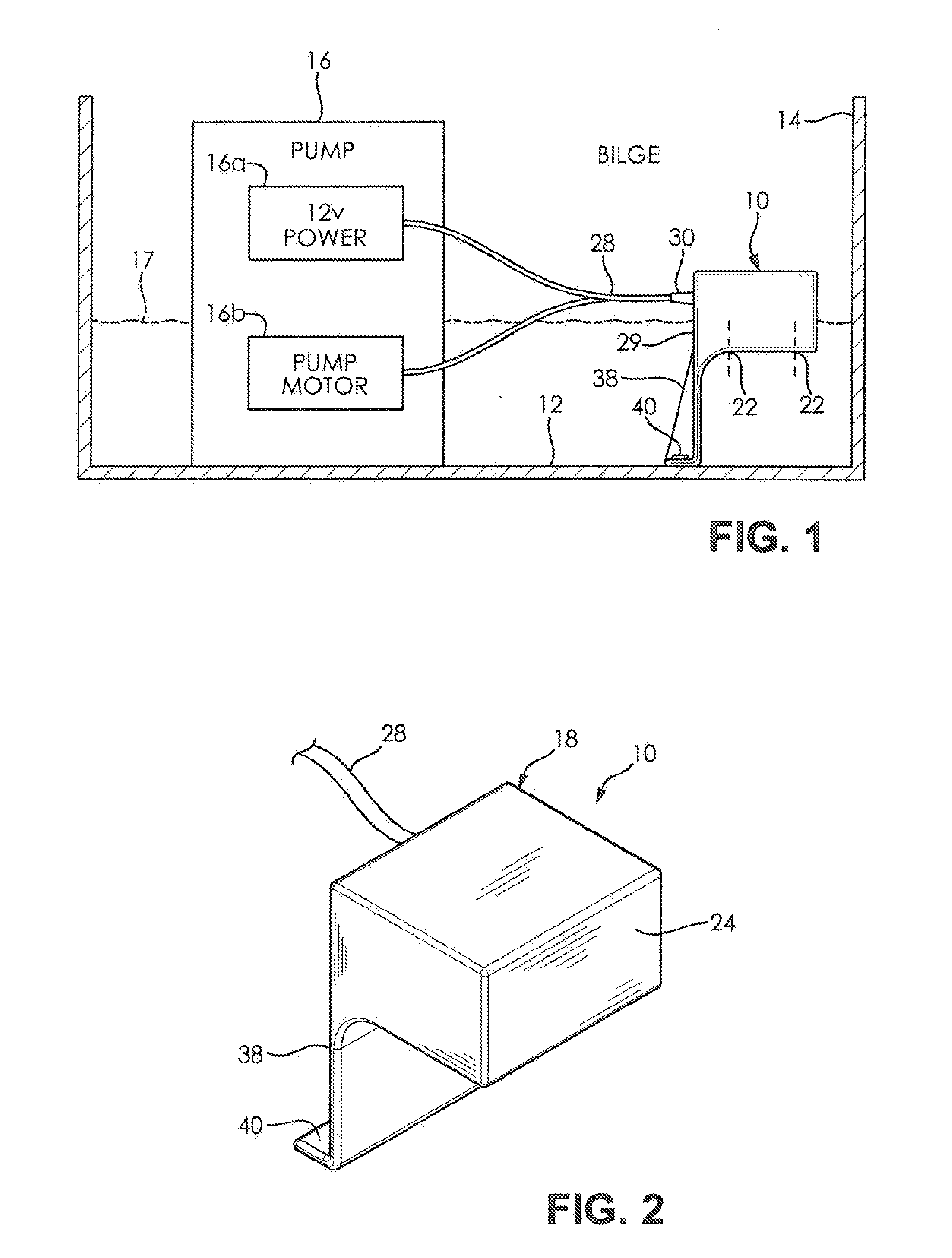
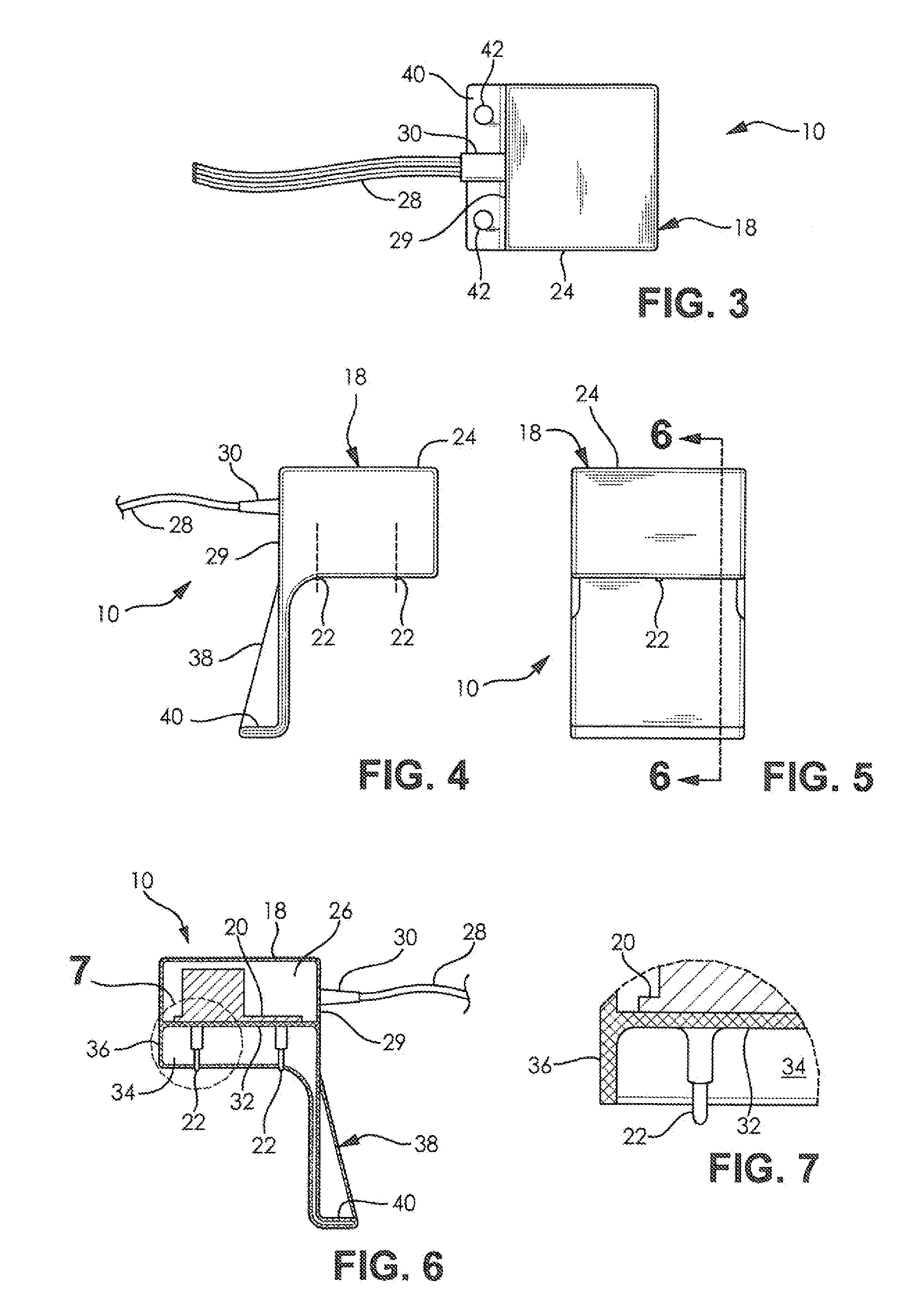
[0023]Referring now to the drawings, FIGS. 1 to 8 illustrate a bilge pump switch 10 according to the present invention. The illustrated bilge switch 10 is mounted at the bottom of a bilge in a boat 14 and is electrically connected to a 12 volt, direct-current bilge pump 16 in order to selectively energize the pump and evacuate the water 17 and other bilge fluids in the bilge 12 of the boat 14. As best shown in FIGS. 2 to 7, the illustrated bilge pump switch 10 includes a protective...


PUM


Abstract

A switch for a bilge pump of a boat includes a pair of probes for providing a probe signal indicating the presence of fluid at the probes, a current sensor for providing a sensor signal indicating electric current of the pump; and a controller programmed to energize the pump when a threshold level of the probe signal indicates the presence of fluid and to de-energize the pump when a threshold level of the sensor signal indicates that the pump is not pumping fluid. The controller can also be programmed to dynamically change the threshold level of the probe signal based on a prior probe signal that indicates changing probe conditions.

Description

CROSS-REFERENCE TO RELATED APPLICATIONS[0001]The application claims the priority benefit of U.S. provisional patent application No. 61 / 492,622 filed on Jun. 2, 2011, the disclosure of which is expressly incorporated herein in its entirety by reference.STATEMENT REGARDING FEDERALLY SPONSORED RESEARCH[0002]Not ApplicablePARTIES TO A JOINT RESEARCH AGREEMENT[0003]Not ApplicableREFERENCE TO APPENDIX[0004]Not ApplicableFIELD OF THE INVENTION[0005]The field of the present invention generally relates to sensors for detecting the presence of fluids for activating a pump, and more specifically, to fluid sensors mounted in boat bilge tanks for activating a bilge pump when bilge fluid reaches a preset level above the bottom of the bilge tank.BACKGROUND OF THE INVENTION[0006]Bilge pumps in boats or ships must be activated before accumulating water reaches an excessive level. Early bilge pumps were activated manually or by mechanical switches such as those that have floats with contacts to compl...

Claims


Application Information

Patent Timeline
IPC IPC(8): F04B49/02
CPCF04B49/02
Inventor NIRENBERG, DAVID B.
Owner LAKE RED ROCK
Why Eureka
Try Eureka