User interface interaction using touch input force

a touch input and user interface technology, applied in the field of user interface interaction using touch input force, can solve the problems of reducing the accuracy and effectiveness of the apr system to efficiently detect touch input, reducing the clarity of the glass screen, and increasing the cost of manufacturing and components

Active Publication Date: 2013-06-06
SENTONS
View PDF19 Cites 180 Cited by
  • Summary
  • Abstract
  • Description
  • Claims
  • Application Information

AI Technical Summary

Problems solved by technology

However, with resistive and capacitive touch detection technologies, the glass screen is required to be coated with a material that reduces the clarity of the glass screen.
Additionally, because the entire glass screen is required to be coated with a material, manufacturing and component costs can become prohibitively expensive as larger screens are desired.
However, the surface glass may pick up other external sounds and vibrations that reduce the accuracy and effectiveness of the APR system to efficiently detect a touch input.
However, sending the ultrasonic waves in the guided pattern increases costs and may be difficult to achieve.
Detecting additional types of inputs, such as multi-touch inputs, may not be possible or may be difficult using SAW or APR technology.
Additionally, current touch detection technology cannot reliably, accurately, and efficiently detect pressure or force of a touch input.
Although prior attempts have been made to detect pressure of touch input by measuring the relative size of a touch input (e.g., as a finger presses harder on a screen, area of the finger contacting the screen proportionally increases), these attempts produce unreliable results when a hard stylus or different sized fingers are used.

Method used


Image

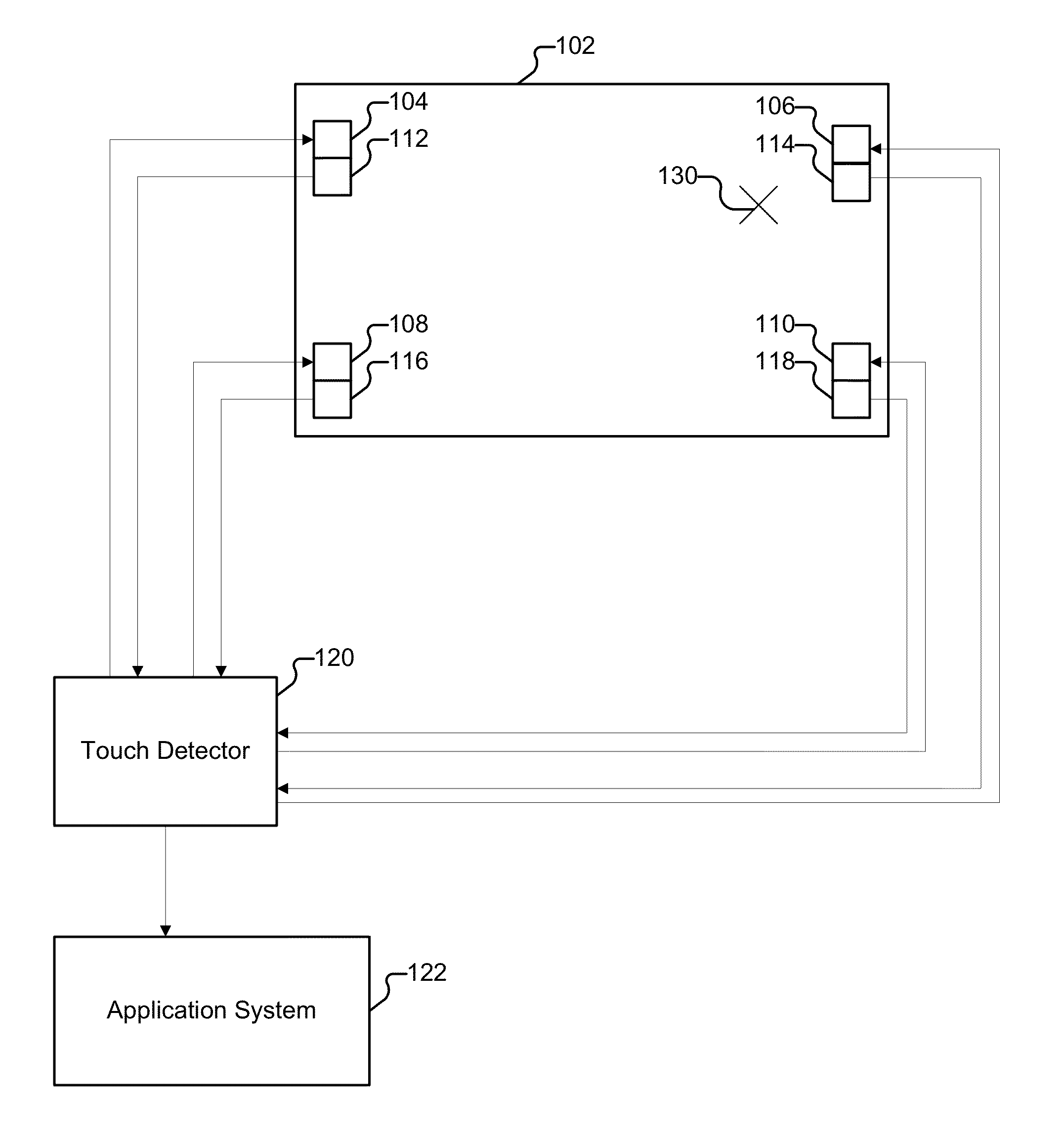
  • User interface interaction using touch input force
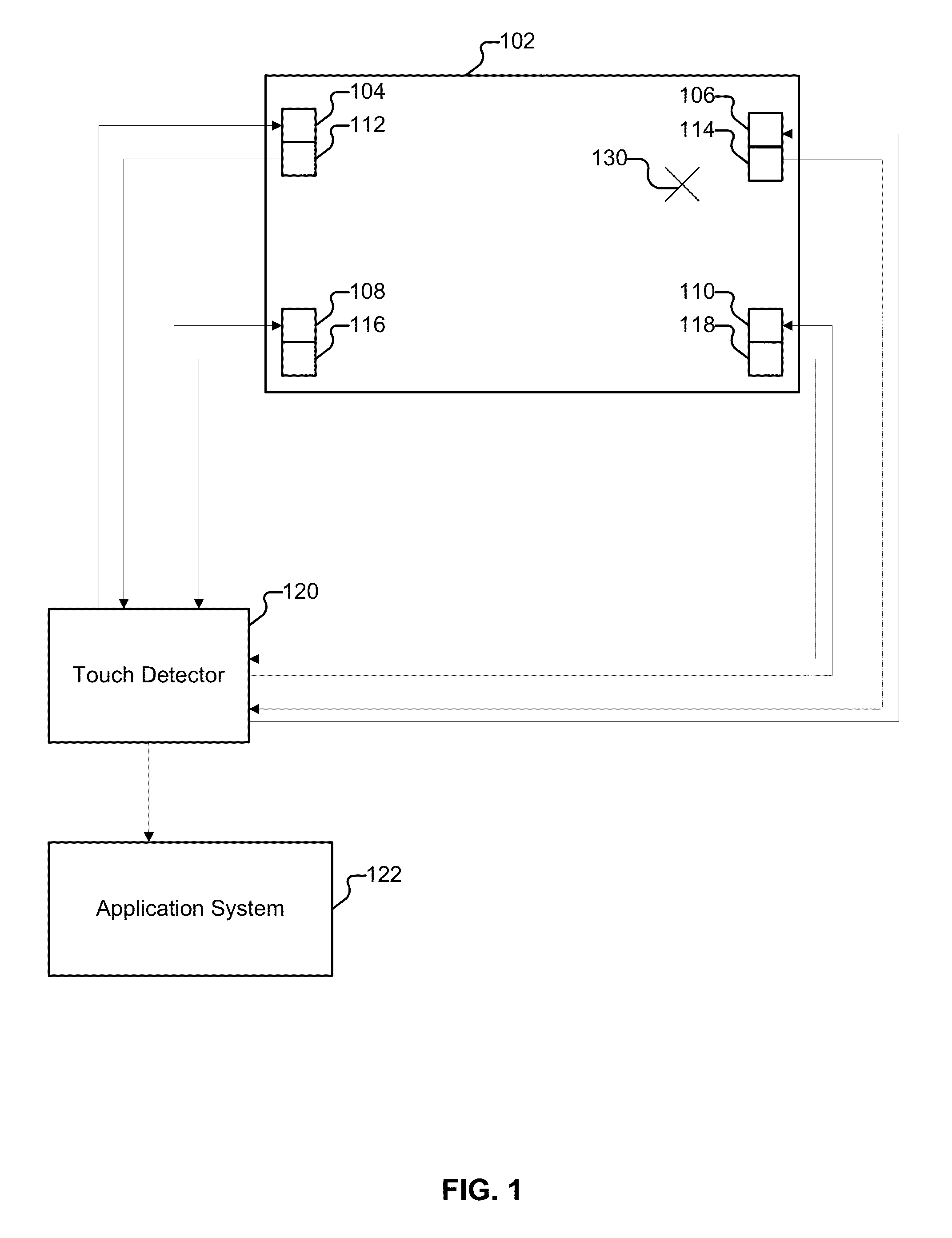
  • User interface interaction using touch input force
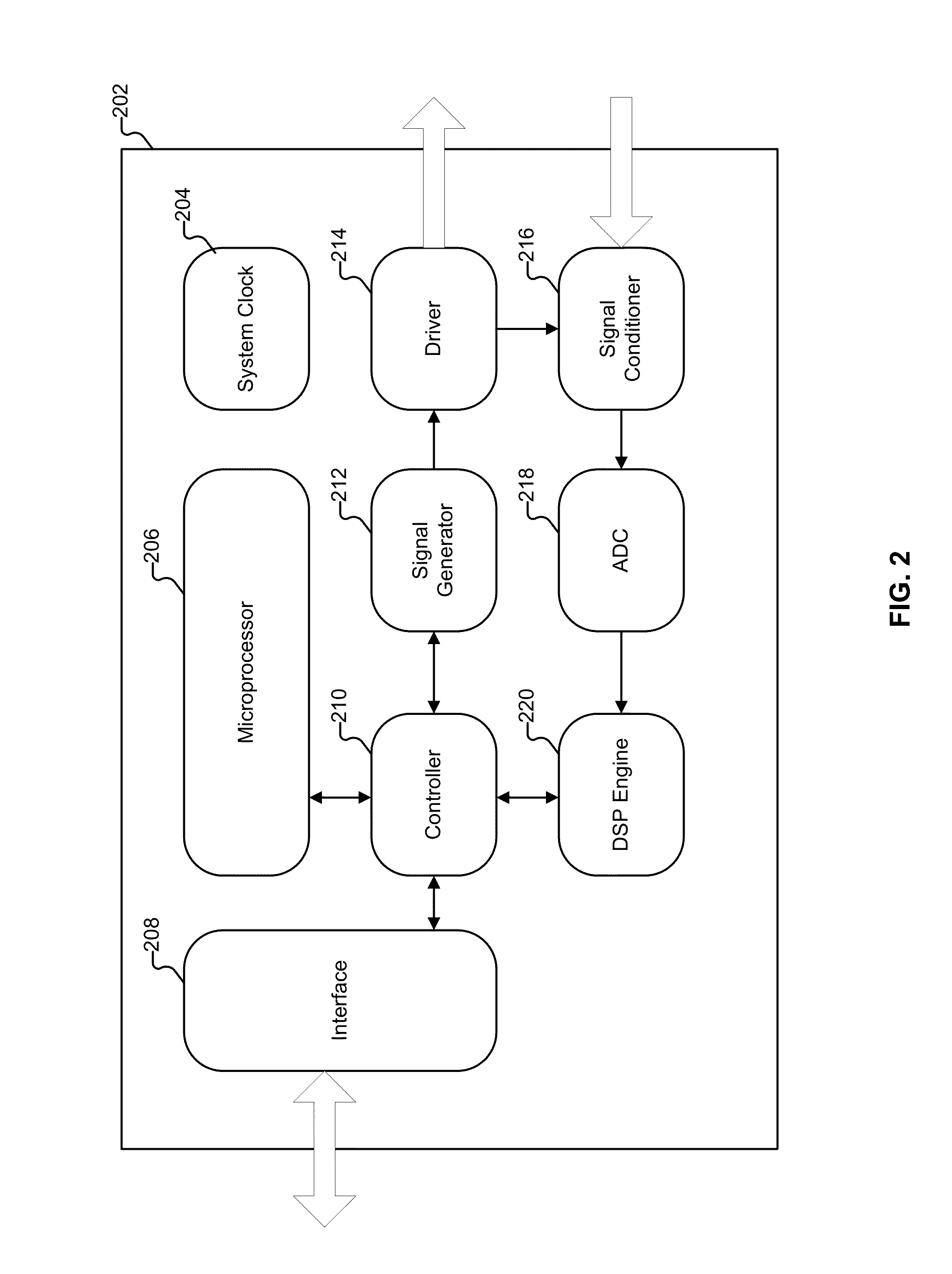
  • User interface interaction using touch input force

Examples


Embodiment Construction

[0026]The invention can be implemented in numerous ways, including as a process; an apparatus; a system; a composition of matter; a computer program product embodied on a computer readable storage medium; and / or a processor, such as a processor configured to execute instructions stored on and / or provided by a memory coupled to the processor. In this specification, these implementations, or any other form that the invention may take, may be referred to as techniques. In general, the order of the steps of disclosed processes may be altered within the scope of the invention. Unless stated otherwise, a component such as a processor or a memory described as being configured to perform a task may be implemented as a general component that is temporarily configured to perform the task at a given time or a specific component that is manufactured to perform the task. As used herein, the term ‘processor’ refers to one or more devices, circuits, and / or processing cores configured to process da...


PUM


Abstract

Providing a user interface interaction is disclosed. A first set of one or more indicators associated with a first location on a touch input surface and a first force intensity of a touch input provided on the touch input surface is received. A user interface object associated with the first location is determined. A second set of one or more indicators associated with a second location on the touch input surface and a second force intensity of the touch input that has been in continuous contact with the touch input surface at least since the touch input was provided at the first location is received. The user interface interaction based at least in part on the user interface object, the first set of indicators, and the second set of indicators is provided.

Description

CROSS REFERENCE TO OTHER APPLICATIONS[0001]This application claims priority to U.S. Provisional Patent Application No. 61 / 561,660 entitled TOUCH SCREEN SYSTEM UTILIZING ADDITIONAL AXIS INFORMATION FOR SELECTED APPLICATIONS filed Nov. 18, 2011 which is incorporated herein by reference for all purposes.[0002]This application claims priority to U.S. Provisional Patent Application No. 61 / 561,697 entitled TOUCH SCREEN SYSTEM UTILIZING ADDITIONAL AXIS INFORMATION filed Nov. 18, 2011 which is incorporated herein by reference for all purposes.[0003]This application claims priority to U.S. Provisional Patent Application No. 61 / 673,102 entitled UTILIZING TOUCH PRESSURE INFORMATION IN GRAPHICAL USER INTERFACES filed Jul. 18, 2012 which is incorporated herein by reference for all purposes.BACKGROUND OF THE INVENTION[0004]Various technologies have been used to detect a touch input on a display area. The most popular technologies today include capacitive and resistive touch detection technology. ...

Claims


Application Information

Patent Timeline
Patent Type & Authority Applications(United States)
IPC IPC(8): G06F3/041
CPCG06F3/041G06F3/0414G06F3/0418G06F3/0436G06F3/043H03G3/02G06F2203/04105G06F3/0482G06F3/0488G06F3/04847G06F3/04886G06F3/0433G06F3/165G06F2203/04106
Inventor LYNN, LAPOE E.SHENG, SAMUEL W.SHIH, SHIH-MINGHSIEH, YENYU
Owner SENTONS
Why Eureka
Try Eureka