

Spinal implant devices and methods
a technology of spinal implants and devices, applied in the field of spinal implants, can solve problems such as pain in the back and lower extremities, and achieve the effect of convenient implantability
- Summary
- Abstract
- Description
- Claims
- Application Information
AI Technical Summary
Benefits of technology
Problems solved by technology
Method used
Image

Examples
Embodiment Construction
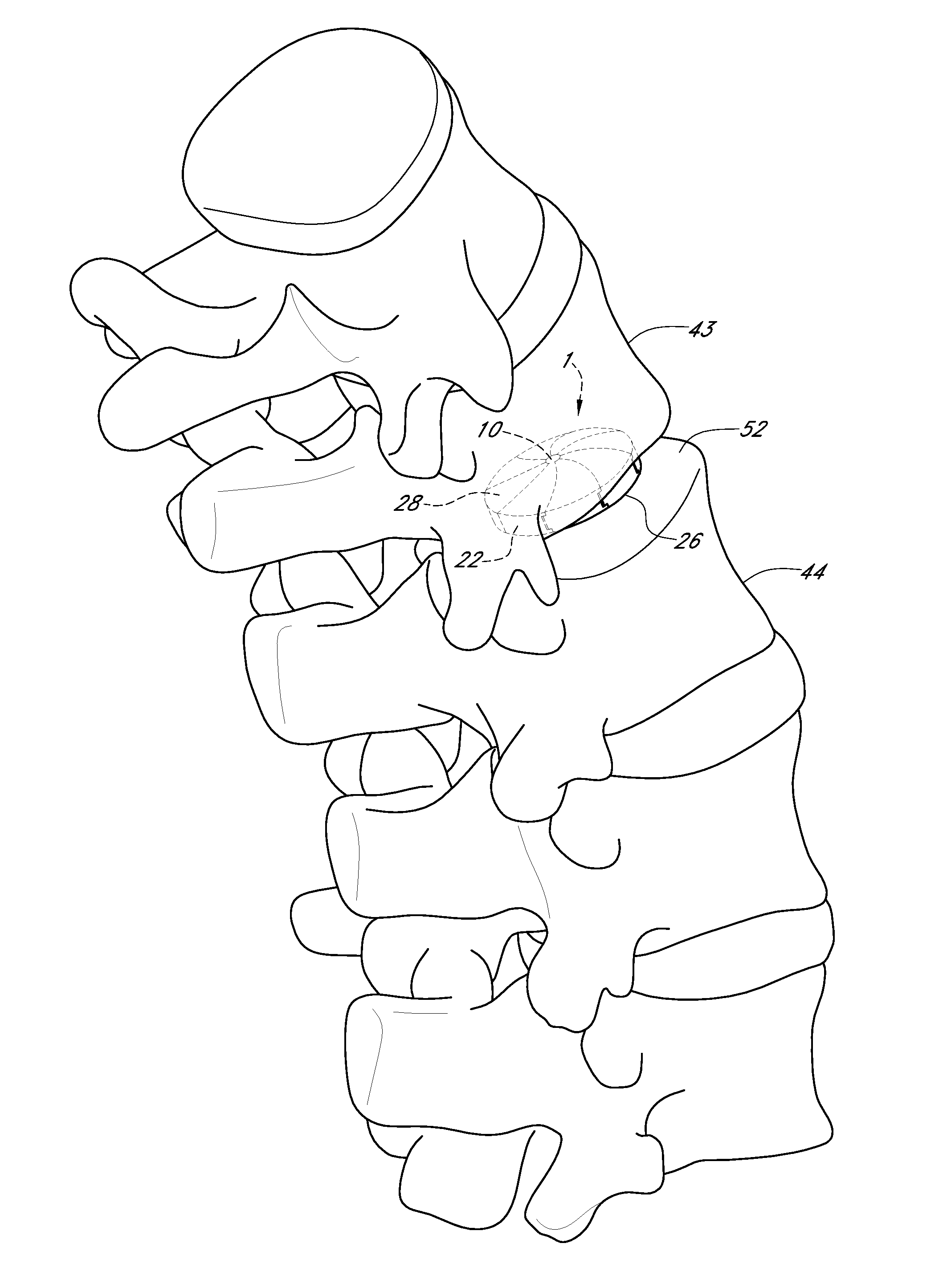
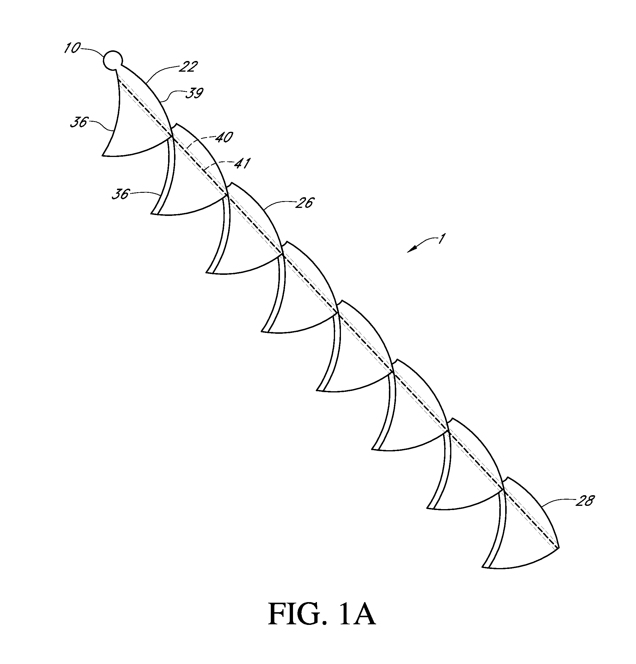
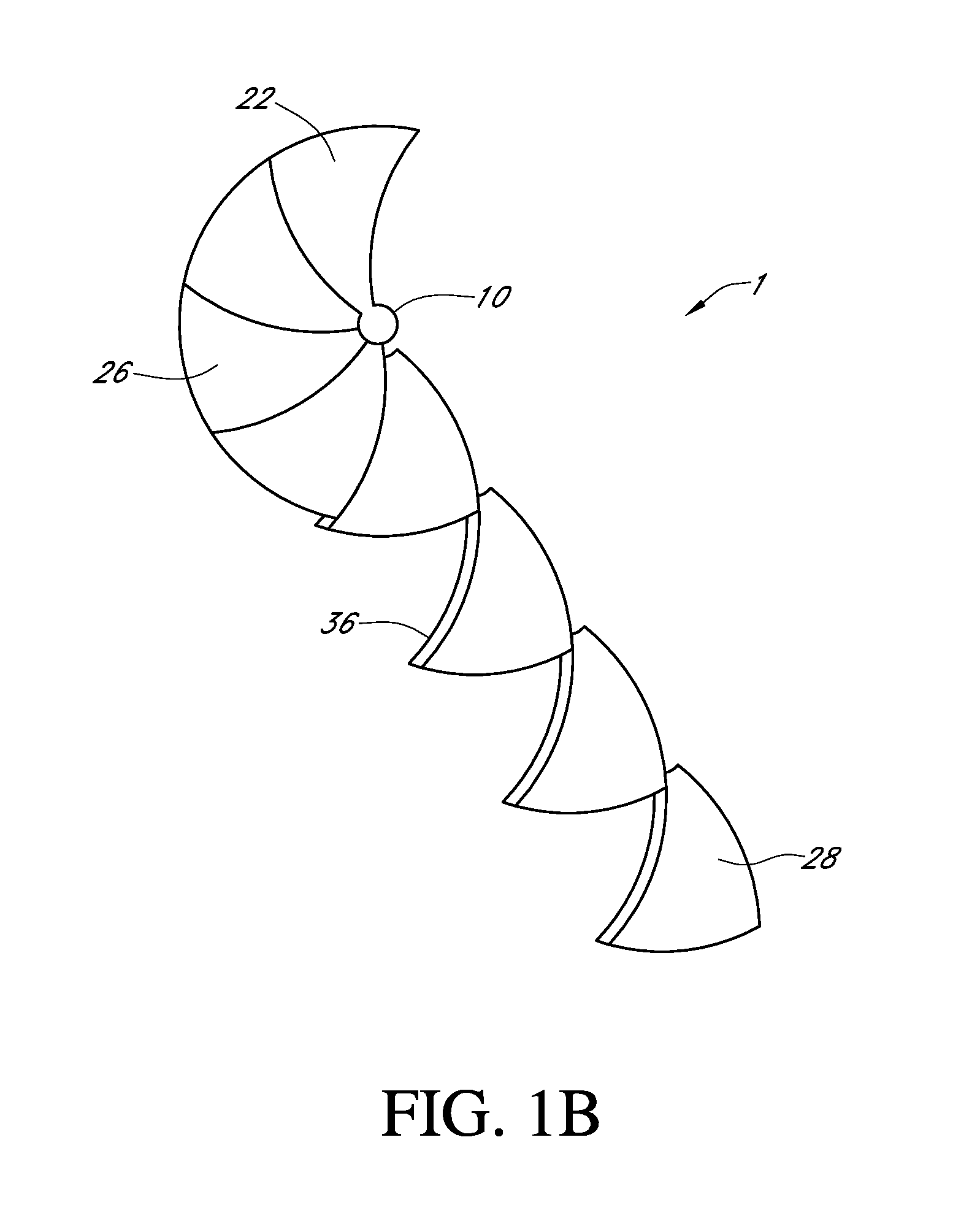
[0007]There is a need to provide an improved spinal implant device that is easily implantable in an intervertebral disc space. According to one embodiment, a spinal implant device preferably comprises a plurality of wedge members coupled in series and configured to allow the wedge members to be delivered to a disc space. The wedge members preferably include surfaces for slidably coupling wedge members so that wedge members rotate circumferentially into position upon delivery to the disc space. The device preferably comprises an anchor to anchor the leading wedge to one or more vertebrae.
[0008]In some embodiments, devices and methods described herein can be used as an improved nucleus replacement device that can replace a degenerated nucleus. The nucleus replacement device preferably acts as a load bearing device, primarily in response to compressive forces, and restores or approximates natural spine biomechanics. In some other embodiments, devices and methods described herein can al...
PUM
 Abstract
Description
Claims
Application Information