Display system and computer-readable medium

a display system and computer-readable medium technology, applied in the field of display systems, can solve the problems of affecting the quality of images, affecting the image quality, and the function of multi-display systems serving as digital signage is temporarily lost, so as to reduce time and cost, improve image quality, and efficient calibrate image content

Active Publication Date: 2013-06-13
SHARP KK
View PDF5 Cites 38 Cited by
  • Summary
  • Abstract
  • Description
  • Claims
  • Application Information

AI Technical Summary

Benefits of technology

[0010]In consideration of these circumstances, the present invention is intended to provide a display system capable of efficiently calibrating image content even when the image content is being reproduced and thereby capable of reducing the time and cost required for the calibration, and to provide a recording medium on which computer programs for causing a computer to perform the calibration are recorded.
[0011]In the case of the present invention, images or regions to be used for calibration are included in a plurality of images of content data. Calibration can be performed while the content data is displayed. Since calibration can be performed while the content data is displayed, it is not necessary to stop image display when the calibration is carried out. In particular, in a display system for use in digital signage or the like that is required to output content at all times, luminance or color can be calibrated without losing the function of the digital signage, whereby an excellent effect is obtained.

Problems solved by technology

In particular, in the case that the display section of a multi-display system being used as digital signage at all times is subjected to calibration, the reproduction of image content for advertisement must be stopped, whereby the function of the multi-display system serving as digital signage is lost temporarily.
In this case, however, the image content is reproduced while the state in which color drift or the like occurs and the quality of the image is deteriorated remains unchanged for a certain period until night time when calibration is performed.

Method used


Image

  • Display system and computer-readable medium
  • Display system and computer-readable medium
  • Display system and computer-readable medium

Examples


embodiment 1

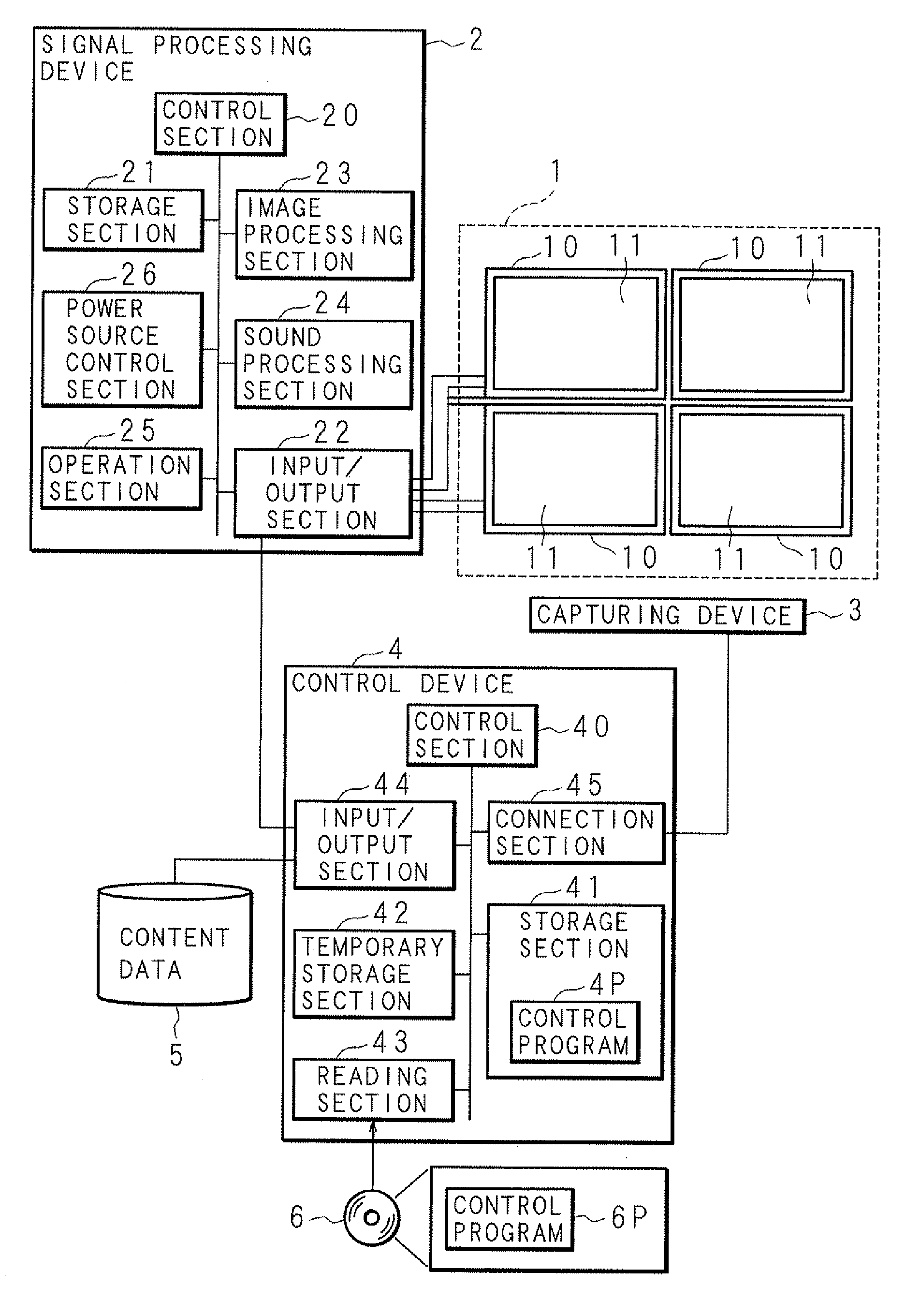
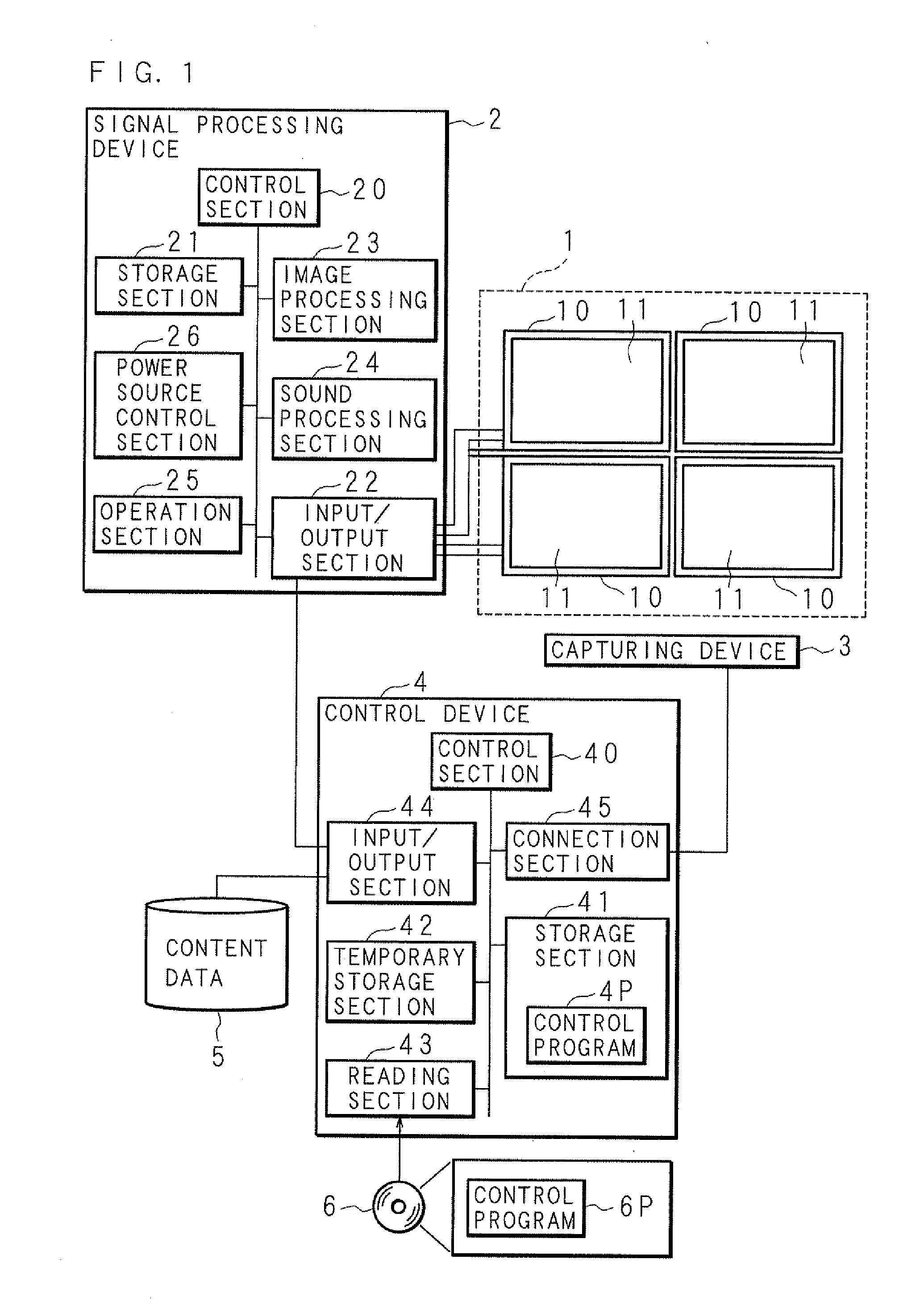
[0048]FIG. 1 is a block diagram showing the configuration of a display system according to Embodiment 1. The display system includes a display section 1 formed of a plurality of display devices 10; a signal processing device 2 for processing image signals to be output to the display devices 10; a capturing device 3 for capturing the display section 1; and a control device 4 for calibrating the luminance or color of images displayed on the group of the display devices 10.

[0049]The display system is used as digital signage, and the display section 1 is thus installed in an easily visible location in a city where people gather. The signal processing device 2 is installed in the vicinity of the display section 1, for example, and connected to the respective display devices 10 of the display section 1 via cables conforming to the system described later. The capturing device 3 is installed so as to use the entire area of the display section 1 as a capturing range. For example, the capturi...

embodiment 2

[0133]In the configuration according to Embodiment 1, a calibration image is inserted or used for replacement ahead of or behind the frame image that is judged first that the calibration image can be produced. In Embodiment 2, a calibration image is inserted or used for replacement ahead of or behind the most similar frame image.

[0134]The configuration of the display system according to Embodiment 2 is similar to that according to Embodiment 1, except for the following processing procedure performed by the control section 40 of the control device 4. Hence, the commonly used components are designated by the same numerals and their detailed descriptions are omitted.

[0135]FIG. 14 is a flow chart showing an example of a processing procedure performed by the calibration image producing section 401 of the control device 4 according to Embodiment 2. Using the function of the calibration image producing section 401, the control section 40 of the control device 4 according to Embodiment 2 pe...

embodiment 3

[0144]In Embodiment 3, a frame image in which a scene change occurs is detected from an image signal based on content data, the so-called cut point detection is performed, and a calibration image is inserted or used for replacement ahead of or behind the frame image at the cut point.

[0145]The configuration of the display system according to Embodiment 3 is similar to that according to Embodiment 1, except for the following processing procedure performed by the control section 40 of the control device 4. Hence, the commonly used components are designated by the same numerals and their detailed descriptions are omitted.

[0146]FIG. 15 is a flow chart showing an example of a processing procedure performed by the calibration image producing section 401 of the control device 4 according to Embodiment 3. Using the function of the calibration image producing section 401, the control section 40 of the control device 4 according to Embodiment 3 performs a process beforehand according to the fo...


PUM


Abstract

The present invention provides a display system capable of efficiently calibrating image content even when the image is displayed and thereby capable of reducing the time and cost required for calibration, and also provides a computer-readable recording medium. The control device thereof processes an image to be displayed on a display section beforehand so as to be usable for calibration. While the image is actually being displayed on the display section, the control device captures an image displayed on the display section using a capturing device at the timing at which a calibration image is displayed, compares the luminance or color in the calibration image with the luminance or color in the image obtained by capturing the calibration image, and creates correction information for correcting an image signal to be output to the display section on the basis of the result of the comparison.

Description

CROSS-REFERENCE TO RELATED APPLICATION[0001]This non-provisional application claims priority under 35 U.S.C. §119(a) on Patent Applications No. 2011-270500 and No. 2011-270502 filed in Japan on Dec. 9, 2011, the entire contents of which are hereby incorporated by reference.BACKGROUND[0002]1. Technical Field[0003]The present invention relates to a display system for calibrating luminance unevenness, color unevenness, etc. on the display sections thereof. More particularly, the present invention relates to a display system capable of performing calibration while content is displayed, and to a recording medium on which computer programs for causing a computer to perform calibration are recorded.[0004]2. Description of Related Art[0005]In recent years, a multi-display system (or a multi-vision system) constituting a single large display screen is used in which a plurality of display devices, each having a display section formed of an LCD (Liquid Crystal Display) or a plasma display, are...

Claims


Application Information

Patent Timeline
Patent Type & Authority Applications(United States)
IPC IPC(8): G09G5/10
CPCG09G5/10G09G3/20G09G2360/147G09G2320/0693G09G2320/0285
Inventor ISHIDA, HIROSHI
Owner SHARP KK
Why Eureka
Try Eureka