Battery cooling structure

a battery module and cooling structure technology, applied in the direction of cell temperature regulation, cell components, electrical devices, etc., can solve the problem of small gap between the cooling surface of the battery module, which is a rigid body, and the cooling pla

Active Publication Date: 2013-06-13
HONDA MOTOR CO LTD
View PDF3 Cites 38 Cited by
  • Summary
  • Abstract
  • Description
  • Claims
  • Application Information

AI Technical Summary

Problems solved by technology

In the case where a cooling surface of a battery module is supported by a hollow cooling plate in which a refrigerant flows, and the battery module is cooled by transferring heat generated in the battery module from the cooling surface to the cooling plate, a small gap is unavoidably formed between the cooling surface of the battery module, which is a rigid body, and the cooling plate, which also is a rigid body.

Method used


Image

  • Battery cooling structure
  • Battery cooling structure
  • Battery cooling structure

Examples


Embodiment Construction

[0020]The embodiments will now be described with reference to the accompanying drawings, wherein like reference numerals designate corresponding or identical elements throughout the various drawings.

[0021]Embodiments of the present application will be described below with reference to FIGS. 1 to 11C.

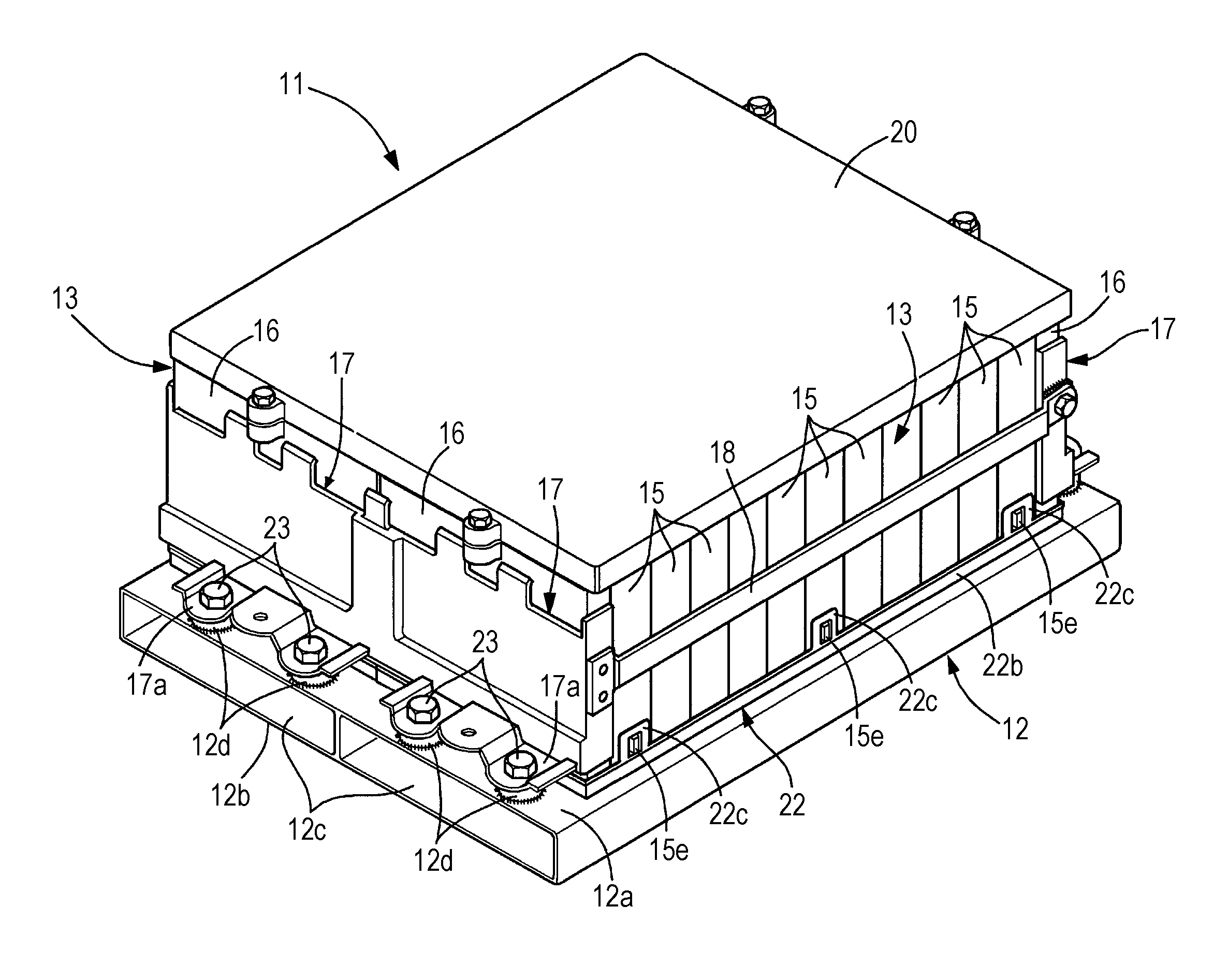
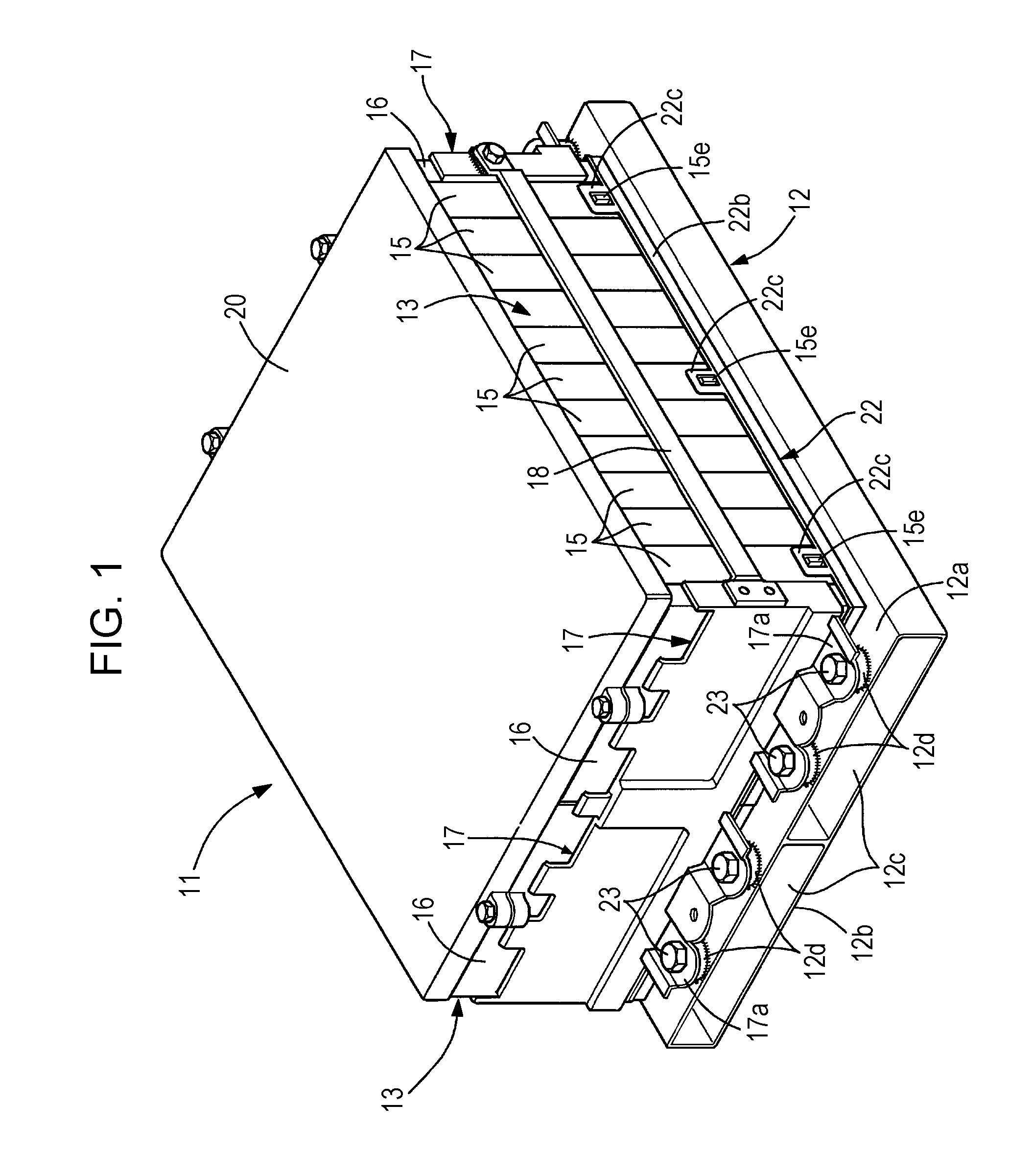
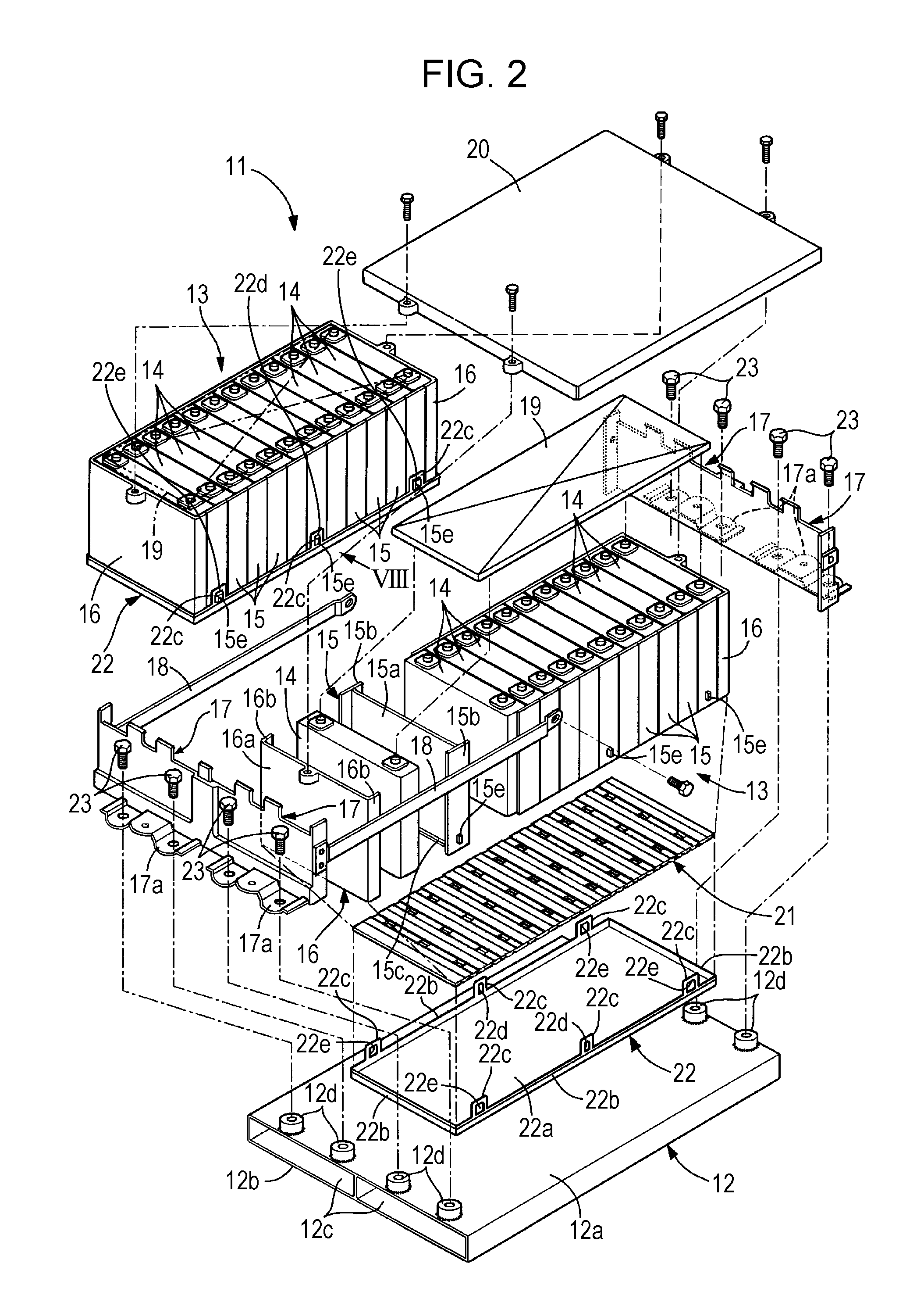
[0022]As illustrated in FIGS. 1 and 2, a battery pack 11, which is to be installed on an electric vehicle, includes a cooling plate 12 and a plurality of battery modules 13, which are supported on the cooling plate 12. Two battery modules 13 and part of the cooling plate 12 are illustrated in FIGS. 1 and 2. Although two battery modules 13, each of which has substantially the same structure, are integrated into a single unit in the present embodiment.

[0023]The battery modules 13 each structured such that a plurality of (12 in the embodiment) box-shaped battery cells 14 are arranged side by side with intermediate holders 15 sandwiched between the battery cells 14 and end holders 16 dispose...


PUM

PropertyMeasurementUnit
thicknessaaaaaaaaaa
thicknessaaaaaaaaaa
electrical non-conductivityaaaaaaaaaa

Abstract

A battery cooling structure includes a cooling plate and an electrically insulative sheet. The cooling plate is to support a cooling surface of a battery module to cool the battery module including a plurality of battery cells arranged side by side. The electrically insulative sheet has an electrical non-conductivity and is disposed between the cooling surface of the battery module and the cooling plate to transfer heat from the cooling surface to the cooling plate.

Description

CROSS-REFERENCE TO RELATED APPLICATIONS[0001]The present application claims priority under 35 U.S.C. §119 to Japanese Patent Application No. 2011-269836, filed Dec. 9, 2011, entitled “Battery Cooling Structure.” The contents of this application are incorporated herein by reference in their entirety.BACKGROUND OF THE INVENTION[0002]1. Field of the Invention[0003]The present application relates to a battery cooling structure.[0004]2. Discussion of the Background[0005]In the case where a cooling surface of a battery module is supported by a hollow cooling plate in which a refrigerant flows, and the battery module is cooled by transferring heat generated in the battery module from the cooling surface to the cooling plate, a small gap is unavoidably formed between the cooling surface of the battery module, which is a rigid body, and the cooling plate, which also is a rigid body. The gap suppresses heat transference between the cooling surface and the cooling plate, thereby degrading the ...

Claims


Application Information

Patent Timeline
Patent Type & Authority Applications(United States)
IPC IPC(8): H01M10/50H01M2/10H01M10/60H01M10/613H01M10/625H01M10/647H01M10/6554H01M10/6556H01M10/6563
CPCH01M10/50H01M10/5004H01M10/5016H01M10/5087H01M10/5046H01M10/5053H01M10/5032H01M10/613H01M10/625H01M10/647H01M10/6551H01M10/6554H01M10/658Y02E60/10
Inventor KIMURA, ARIHISAKATAYAMA, GOICHIYAMAMOTO, KOICHIFUJIOKA, MASATO
Owner HONDA MOTOR CO LTD
Why Eureka
Try Eureka