Low bandgap, monolithic, multi-bandgap, optoelectronic devices

a low bandgap, monolithic technology, applied in the direction of semiconductor/solid-state device manufacturing, semiconductor/solid-state device manufacturing, electrical apparatus, etc., can solve the problems of reducing energy conversion efficiency, large inefficiencies and energy losses to unwanted heat, and knowledge alone cannot solve the problem of making an efficient and useful energy conversion devi

Inactive Publication Date: 2006-07-27
ALLIANCE FOR SUSTAINABLE ENERGY
View PDF37 Cites 295 Cited by
  • Summary
  • Abstract
  • Description
  • Claims
  • Application Information

AI Technical Summary

Benefits of technology

[0024] The first subcell is preferably a lattice-matched, double-heterostructure, comprising homojunction layers of GaInAs(P) clad by InAsyP1-y cladding layers wherein the InAsyP1-y cladding has a value for y in a range of o≦y<1, such the InAsyP1-y cladding layers of the first subcell have a lattice constant equal to the first lattice constant. The second subcell is is also preferably a lattice-matched, double-heterostructure comprising homojunction layers of GaInAs(P) clad by InAsyP1-y cladding layers, wherein the InAsyP1

Problems solved by technology

However, since solar radiation and blackbody radiation usually comprise a wide range of wavelengths, use of only one semiconductor material with one bandgap to absorb such radiant energy and convert it to electrical energy will result in large inefficiencies and energy losses to unwanted heat.
Semiconductor compounds and alloys with bandgaps in the various desired energy ranges are known, but that knowledge alone does not solve the problem of making an efficient and useful energy conversion device.
Defects in crystalline semiconductor materials, such as impurities, dislocations, and fractures provide unwanted recombination sites for photogenerated electron-hole pairs, resulting in decreased energy conversion efficiency.
Lattice-mismatching (LMM) in adjacent crystal materials causes lattice strain, which, when high enough, is usually manifested in dislocations, fractures, wafer bowing, and other problems that degrade or destroy electrical characteristics and capabilities of the device.
Unfortunately, the semiconductor materials that have the desired bandgaps for absorption and conversion of radiant energy in some energy or wavelength bands do not always lattice match other semiconductor materials with other desired bandgaps for absorption and conversion of radiant energy in other energy or wavelength bands.
Therefore, fabrication of

Method used


Image

  • Low bandgap, monolithic, multi-bandgap, optoelectronic devices
  • Low bandgap, monolithic, multi-bandgap, optoelectronic devices
  • Low bandgap, monolithic, multi-bandgap, optoelectronic devices

Examples


embodiment 110

[0082] As mentioned above, the numbers and combinations of subcells and lattice constant transition layers as well as the specific example bandgap values shown in the PV converter 112 of FIG. 5 are selected arbitrarily to illustrate the principles of this invention. The only requirement is that the incident radiation reaches the subcells in order of decreasing bandgaps, so that the shorter wavelength radiation is absorbed and converted to electricity by higher bandgap subcells that will transmit unabsorbed, longer wavelength radiation to the next subcell(s). Other details, such as buffer layers, tunnel junction or isolation layers, contacts, optic control layers, etc., for fabricating a working PV converter can be similar to those described above for either the series connected subcell embodiments 10 of FIGS. 1 and 2 or the independently connected subcell embodiment 110 of FIG. 4.

embodiment 10

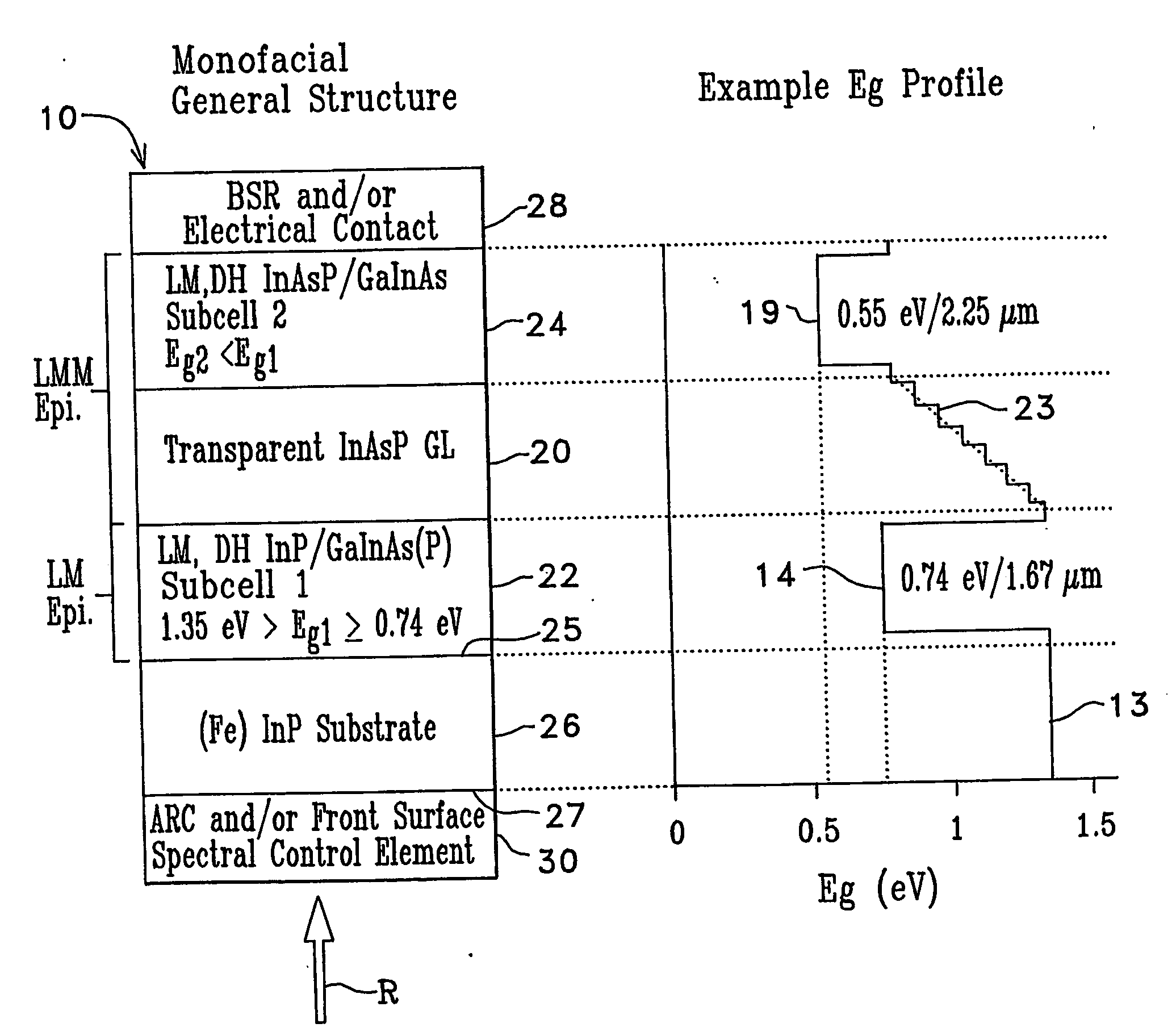
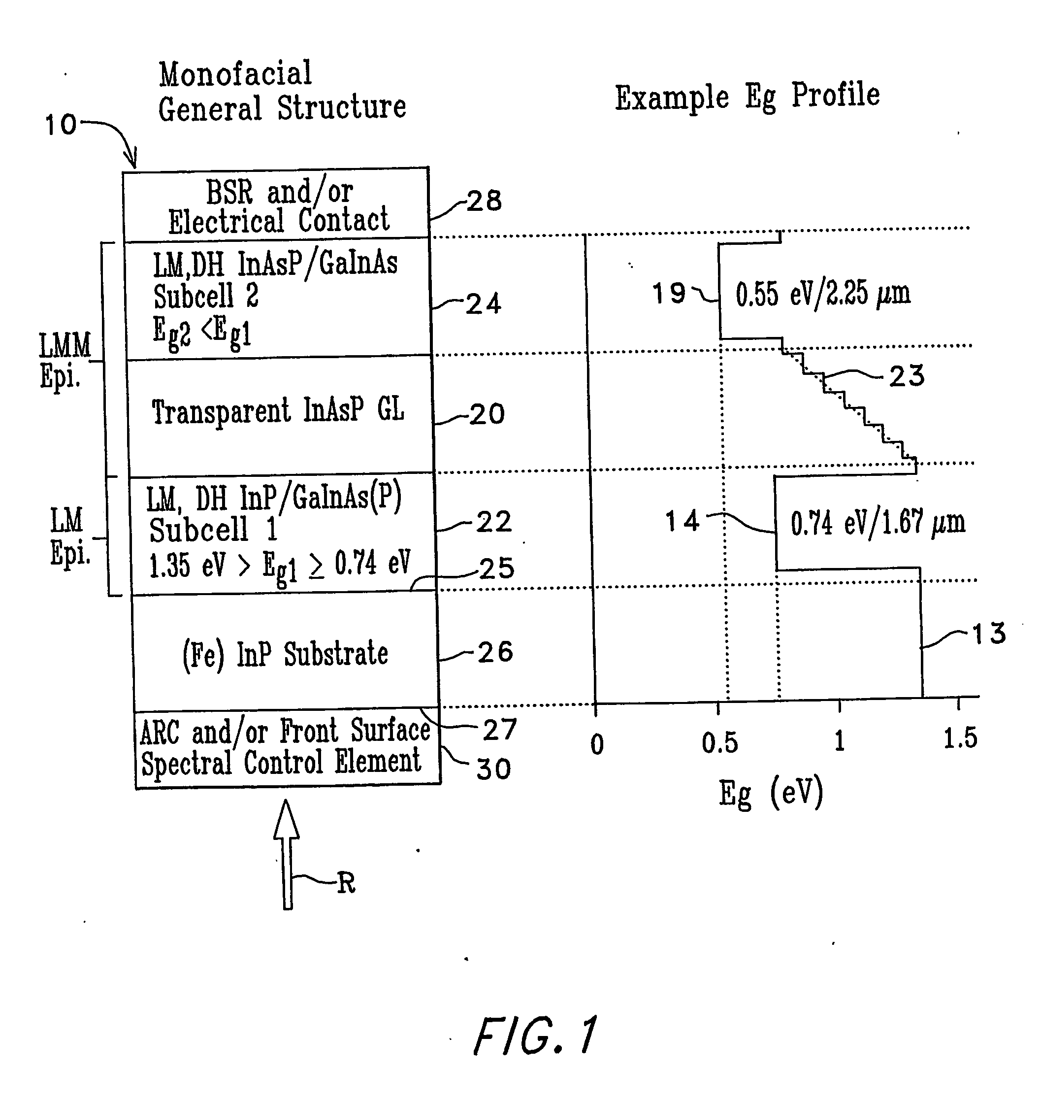
[0083] Now, as illustrated in another alternative inverted, monofacial, multi-bandgap, PV converter 140 in FIG. 6, the positions of the transparent lattice constant transition layer 20 and the first subcell 22 positions can be reversed from their positions shown in the FIG. 1 embodiment 10. Specifically, the lattice constant transition layer 20 can be grown expitaxially on the InP substrate 26 by gradually adding more and more As to the growing InAsyP1-y lattice constant transition layer 20, as described above, until a desired lattice constant is attained for a desired GaxIn1-xAs or GaxIn1-xAsyP1-y semiconductor material with a desired bandgap to be grown on the InP substrate 26. As explained above, the desire bandgap is chosen for absorbing and converting infrared radiation R of a desired wavelength or frequency band to electricity.

[0084] For example, but not for limitation, if it is desired to have the first subcell 22 in the PV converter 140 of FIG. 6 absorb and convert infrared ...

embodiment 140

[0089] This invention, as mentioned above, also extends to low bandgap, monolithic, multi-bandgap PV converters with more than one lattice constant transition layer. For example, referring again to FIG. 6, one or more additional subcells with even lower bandgap(s) than the 0.58 eV bandgap of the second subcell 24 can be grown on top of subcell 24. Such an example PV converter 150 with three subcells 22, 24, 72 is illustrated diagrammatically in FIG. 8. This example three-bandgap PV converter 150 is illustrated for convenience with the same substrate 26, first lattice constant transition layer 20, first subcell 22, and second subcell 24 as the two-bandgap embodiment 140 of FIG. 6, but it has a second lattice constant transition layer 70 positioned between the second subcell 24 and a third subcell 72.

[0090] As was explained above in relation to the inverted tandem (two-subcell) PV converter 140 in FIG. 6, the InP substrate 26 and the first lattice constant transition layer 20 are tran...


PUM


Abstract

Low-bandgap, monolithic, multi-bandgap, optoelectronic devices (10), including PV converters, photodetectors, and LED's, have lattice-matched (LM), double-heterostructure (DH), low-bandgap GaInAs(P) subcells (22, 24) including those that are lattice-mismatched (LMM) to InP, grown on an InP substrate (26) by use of at least one graded lattice constant transition layer (20) of InAsP positioned somewhere between the InP substrate (26) and the LMM subcell(s) (22, 24). These devices are monofacial (10) or bifacial (80) and include monolithic, integrated, modules (MIMs) (190) with a plurality of voltage-matched subcell circuits (262, 264, 266, 270, 272) as well as other variations and embodiments.

Description

CONTRACTUAL ORIGIN OF INVENTION [0001] The United States Government has rights in this invention under Contract No. DE-AC36-99GO10337 between the United States D Renewable Energy Laboratory, a Division of the Midwest Research Institute.TECHNICAL FIELD [0002] This invention relates to optoelectronic devices, and, more specifically, to low bandgap, monolithic, multi-bandgap solar photovoltaic (SPV) and thermophotovoltaic (TPV) cells for converting solar and / or thermal energy to electricity as well as for related photodetector devices for detecting light signals and light emitting diode (LED) devices for converting electricity to light and / or infrared (IR) radiant energy. BACKGROUND OF THE INVENTION [0003] It is well known that the most efficient conversion of radiant energy to electrical energy with the least thermalization loss in semiconductor materials is accomplished by matching the photon energy of the incident radiation to the amount of energy needed to excite electrons in the s...

Claims


Application Information

Patent Timeline
IPC IPC(8): H01L31/00
CPCH01L31/06875Y02E10/544H01L31/0725H01L31/046H01L31/03046H01L31/0687H01L31/043H01L31/0475
Inventor WANLASS, MARK W.CARAPELLA, JEFFREY J.
Owner ALLIANCE FOR SUSTAINABLE ENERGY
Why Eureka
Try Eureka