
Slickline or Wireline Run Hydraulic Motor Driven Mill

a hydraulic motor and motor drive technology, applied in the field of mills, can solve the problems of coiled tubing units that are often not at a well site, are very expensive to deploy, and have obvious safety issues, and damage the outer string on the back side of the tubing being cu

Active Publication Date: 2013-06-20
BAKER HUGHES INC
View PDF3 Cites 17 Cited by
  • Summary
  • Abstract
  • Description
  • Claims
  • Application Information

AI Technical Summary

Benefits of technology

The patent text describes a device for cutting and milling tubing in a wellbore. It includes a tool that is lowered into the tubing to be cut using a fluid pumped from the surface. The device has blades that rotate to cut the tubing as the fluid flows through the device. The device can also be used to mill fish in the tubing using a telescoping assembly that is pushed against the fish using springs. Overall, the device allows for efficient and safe cutting and milling of tubing in wellbore operations.

Problems solved by technology

Coiled tubing units are frequently not at a well site and are very expensive to deploy.
These designs had the obvious safety issues of dealing with explosives.
The extension reach of the explosion could damage the outer string on the back side of the tubing being cut.

Method used


Image

  • Slickline or Wireline Run Hydraulic Motor Driven Mill
  • Slickline or Wireline Run Hydraulic Motor Driven Mill
  • Slickline or Wireline Run Hydraulic Motor Driven Mill

Examples


Embodiment Construction

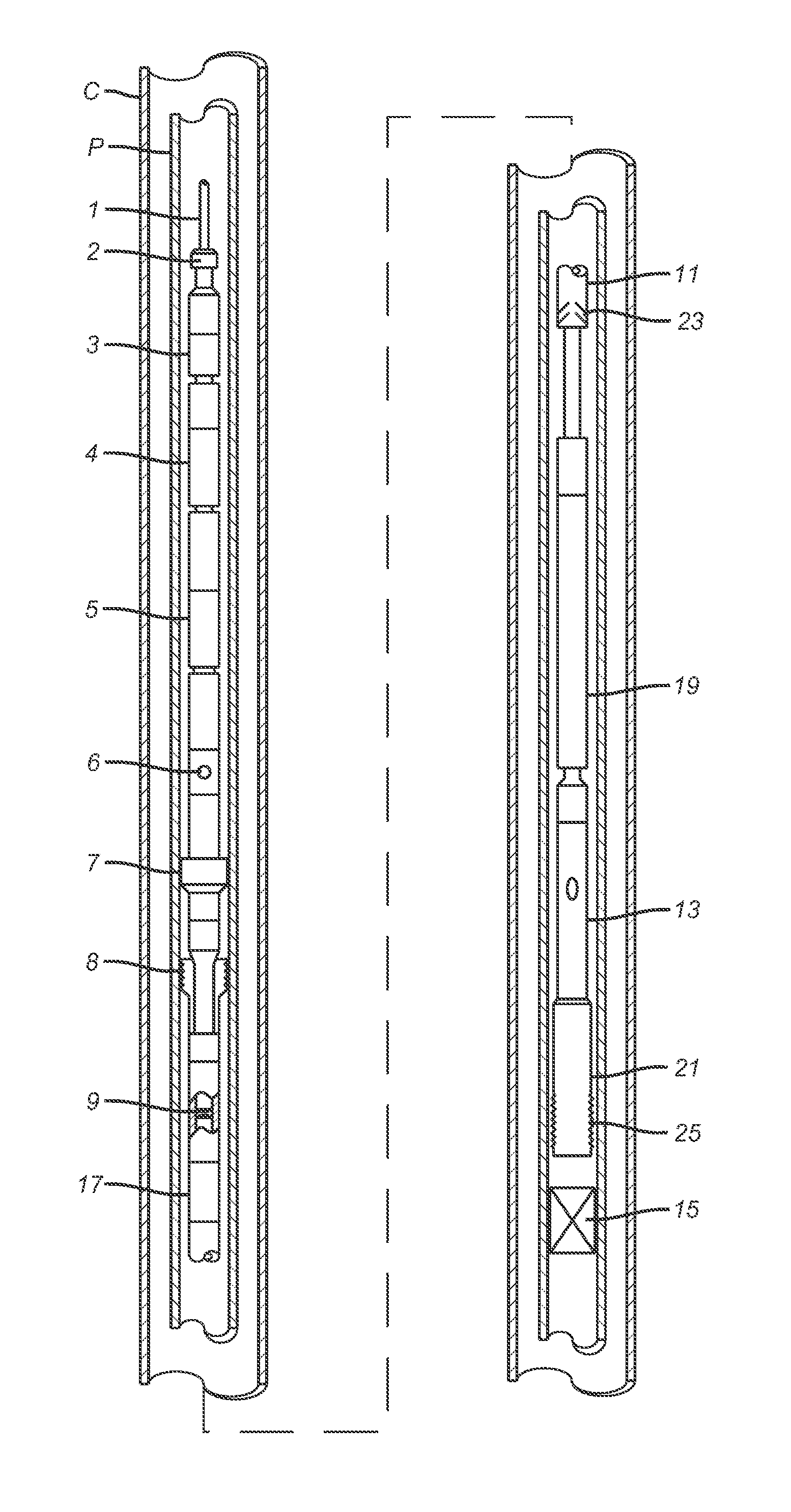
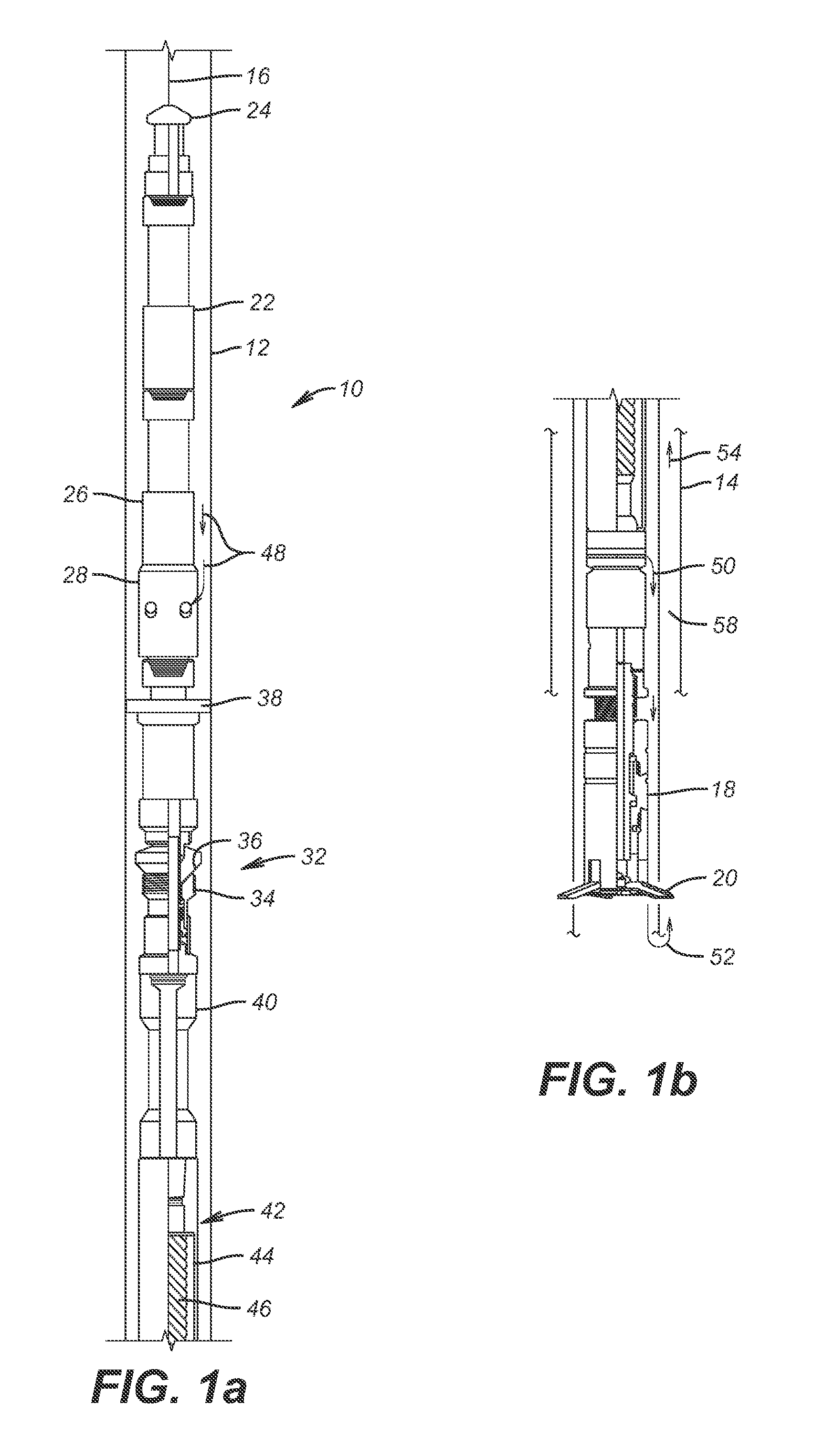
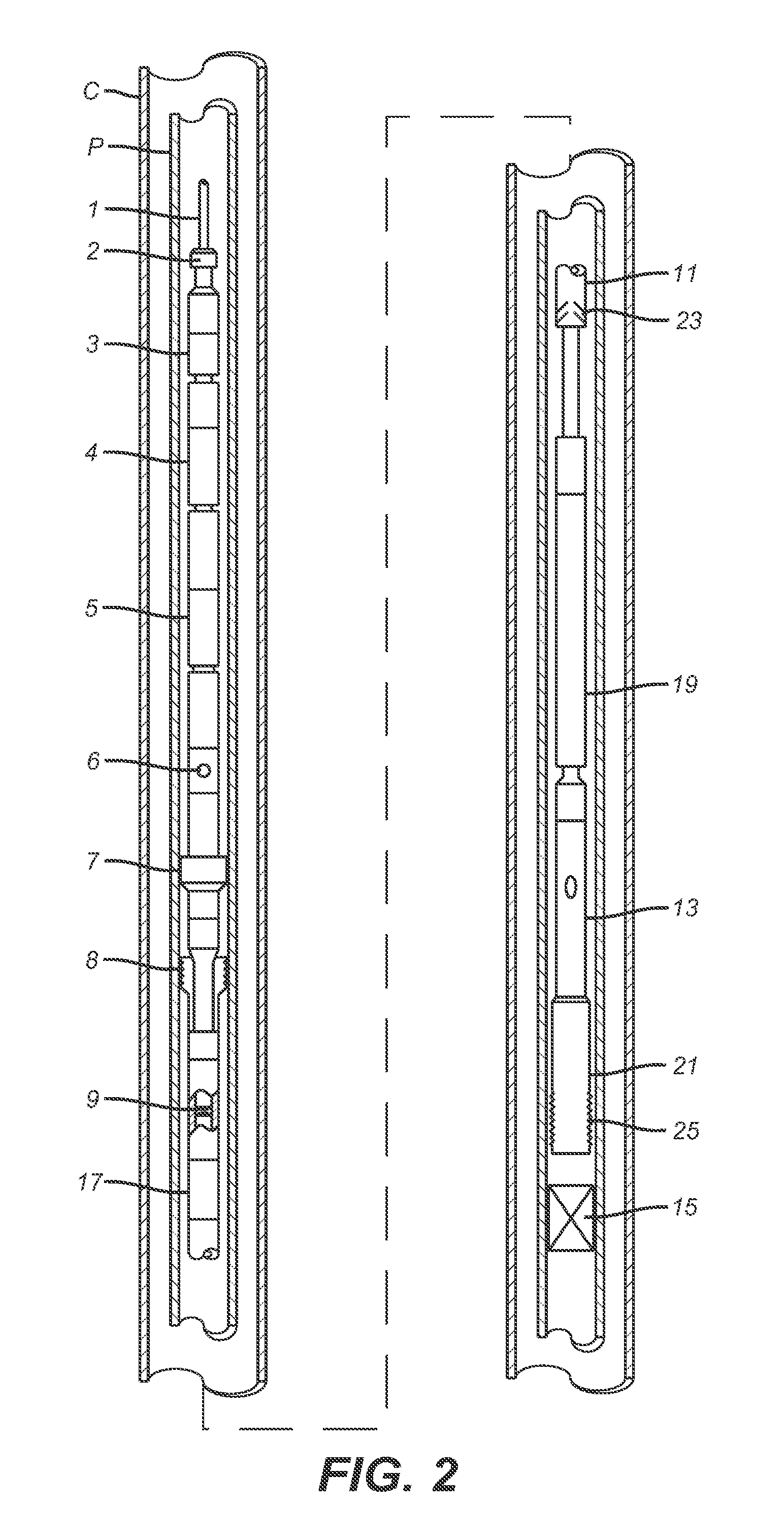
[0016]In one embodiment, the cutter assembly 10 is preferably positioned in a tubular string 12 that is disposed in a surrounding string such as casing 14 shown in part in FIG. 1a. A slickline 16 or alternatively a wireline, if available at the surface, supports the illustrated equipment down to the cutter 18 shown in FIG. 1a with cutting blades 20 extended into the cutting position. The slickline 16 supports an optional accelerator 22 for use in shallow depth applications. Other familiar components when running slickline are employed in the assembly 10 such as a fishing neck 24 and a jar tool such as 26. The jar tool 26 allows jarring to get unstuck while the fishing neck 24 allows the assembly to be fished out if the jar tool 26 does not help it break loose. A ported sub 28 has ports 30 that preferably stay open.

[0017]The equipment shown below the ported sub 28 is schematically illustrated to perform a sealing function in string 12 so that fluid pumped from the surface will go int...


PUM


Abstract

A tool is run in with a bottom hole assembly that includes a seal and support within the tubing where a fish is to be milled. A ported sub allows pressurized fluid pumped from the surface to enter the bottom hole assembly above the sealed support location and to be directed to set an anchor and to a fluid driven motor such as a progressive cavity motor that is in turn connected milling tool at the rotor of the progressive cavity motor. The fluid exiting the stator goes through a debris removal device and can return to the surface through an annulus around the production tubing. A telescoping joint allows the mill to axially progress with a force applied to the fish generated by a tractor or a stack of Belleville washers.

Description

CROSS REFERENCE TO RELATED APPLICATION[0001]This application is a continuation-in-part of U.S. patent application Ser. No. 12 / 795,292, filed on Jun. 7, 2010, and claims the benefit of priority from the aforementioned application.FIELD OF THE INVENTION[0002]The field of this invention is mills and more specifically those that are rotatably driven by a bottom hole assembly suspended from the surface with a cable or wireline while a motor in the assembly powers the mill using fluid flow into the tubular and most specifically a washover mill with an advancing feature in the bottom hole assembly (BHA) to advance the mill as the milling progresses.BACKGROUND OF THE INVENTION[0003]Tubing cutters have been run into a subterranean location into tubing that is to be cut on coiled tubing and / or tubular. The coiled tubing or tubular has fluid pumped through it to power a downhole motor that is fluid driven such as a progressing cavity pump. The rotation of the pump drives the cutter after exten...

Claims


Application Information

Patent Timeline
Patent Type & Authority Applications(United States)
IPC IPC(8): E21B29/00E21B31/00
CPCE21B29/002E21B29/005E21B31/00
Inventor LAIRD, MARY L.COLBERT, ROBBIE B.COLEMAN, DAVID W.
Owner BAKER HUGHES INC
Learn More