Blowing Machine Valve

a blowing machine and valve body technology, applied can solve the problems of high cost of using two compressors, inconvenient method, and many problems in the field of container blowing facilities, and achieve the effect of improving the known device and reducing the volume and cost of the valv

Inactive Publication Date: 2013-06-20
TECHNOPLAN ENG
View PDF3 Cites 0 Cited by
  • Summary
  • Abstract
  • Description
  • Claims
  • Application Information

AI Technical Summary

Benefits of technology

[0012]The aim of the invention is to improve the kno...

Problems solved by technology

Many problems exist in the field of container blowing facilities.
However, using two compressors is expensive both in terms of the initial investment to purchase them and their upkeep.
This method is also not particularly advantageous, since energy is wasted to compress a gas whereof the pressure is reduced without having been used in the manufacturing process.
Furthermore, once the container has been formed by blowing,...

Method used


Image

  • Blowing Machine Valve
  • Blowing Machine Valve
  • Blowing Machine Valve

Examples


Embodiment Construction

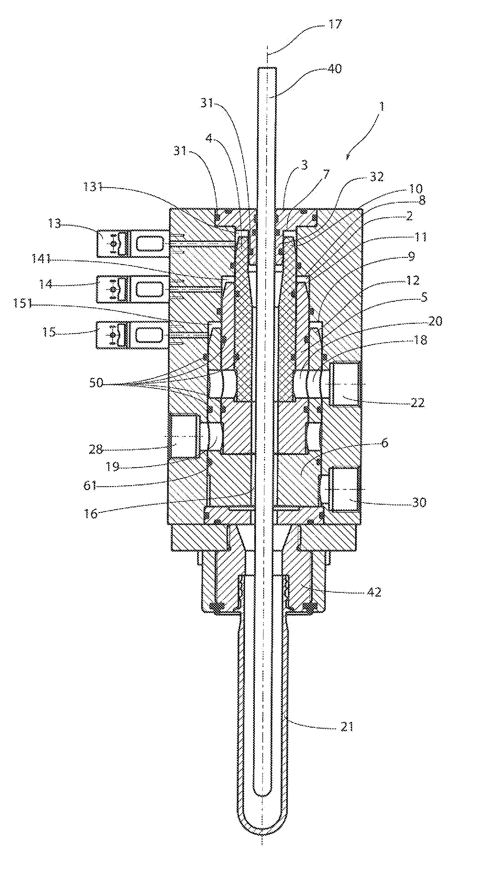
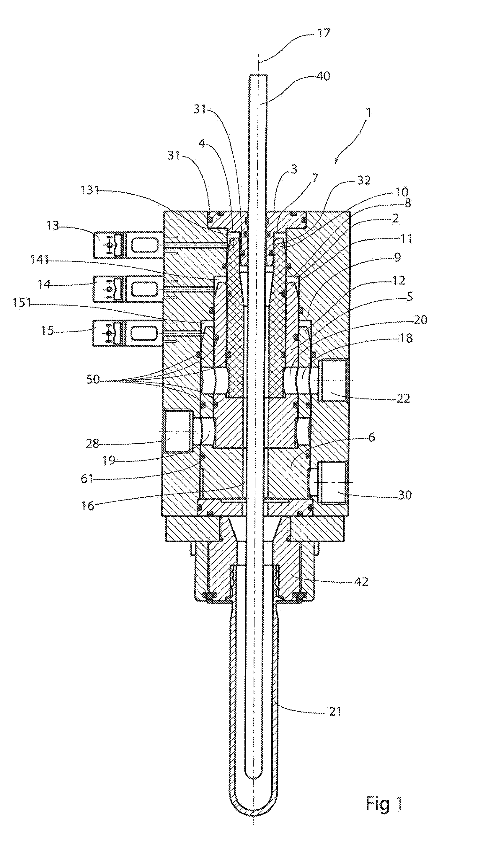
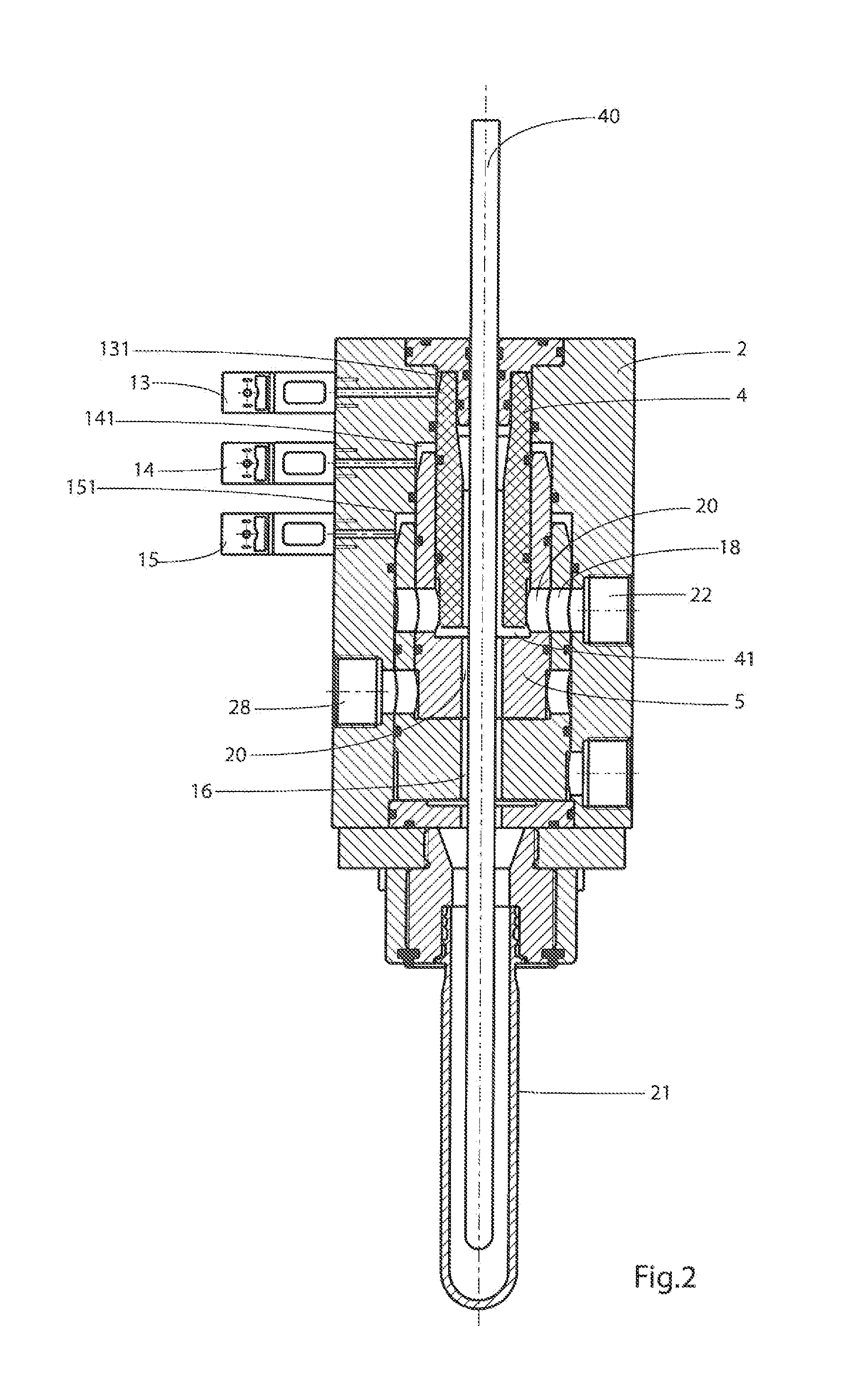
[0028]The valve is first described in reference to FIG. 1. This valve comprises a valve body 1 with a generally cylindrical chamber 2, with an axis 17 and a lid 3. Inside the chamber 2, there are three cylindrical sleeves 4, 5 and 6 that are movable along the axis 17. The upper sleeve 4 is located inside the following sleeve 5, which in turn is located inside the third sleeve 6. The three sleeves 4, 5, 6 can move relative to one another and relative to the inner wall of the chamber 2 in a sealed manner owing to several circular sealing gaskets 61,, The hollow portion of these three sleeves forms a channel 16 for the passage of the blowing gas. The lid 3 comprises a hollow cylindrical narrow part 32 housed in the upper portion of the sleeve 4, The hollow portion of the stopper 3 contributes to the continuity of the channel 16. Circular sealing gaskets 31 guarantee sealing of the assembly of the lid with the valve body 2 and the sleeve 4. In the chamber 2, there are two circular shoul...


PUM


Abstract

The present invention relates to a valve for a machine for blowing containers, comprising a hollow valve body with an axis, a lid, at least two sleeves moving along said axis in said chamber, at least one inlet and one outlet, and control means designed to move said sleeves in said chamber. The sleeves are mounted one inside the other and they form a channel for the passage of a blowing gas. Each sleeve containing another sleeve has at least one radial passage for passage of the blowing gas when it is aligned with said inlet.

Description

[0001]This application claims priority benefits to French Patent Application 11 61637 filed Dec. 14, 2011, the entire disclosure of which is incorporated herein by reference.FIED OF THE INVENTION[0002]The present invention relates to a valve for a machine for blowing containers, comprising a hollow valve body forming a generally cylindrical chamber with an axis, a lid, and at least two sleeves moving along said axis in said chamber, at least one inlet and one outlet, and control means making it possible to move said sleeves in said chamber, the position of said sleeves defining the open or closed state of said at least one inlet and said outlet.DESCRIPTION OF THE PRIOR ART[0003]Many problems exist in the field of container blowing facilities. First, it is necessary to have a gas, such as air, at a high pressure in the vicinity of 40 bar to blow the containers in a mold. Traditionally, compressors are used to compress the necessary gas. However, in some blowing methods, pre-blowing o...

Claims


Application Information

Patent Timeline
IPC IPC(8): B29C49/42
CPCF16K11/20B29L2031/7506B29C49/06F16K31/1225B29C49/12B29C49/4289B29C2949/0715
Inventor JOVER, DANIELBOHRER, PIERRE
Owner TECHNOPLAN ENG
Why Eureka
Try Eureka