Keyboard, Method of Driving and Assembling the Same, and Electronic Device

a driving method and keyboard technology, applied in the field of electronic devices, can solve the problems of not being used anymore, prone to aging, poor hand feeling, etc., and achieve the effects of reducing the risk of aging, and prolonging the service li

Active Publication Date: 2013-06-20
LENOVO (BEIJING) LTD +1
View PDF6 Cites 26 Cited by
  • Summary
  • Abstract
  • Description
  • Claims
  • Application Information

AI Technical Summary

Benefits of technology

[0034]With the keyboard, the driving and assembling methods of the keyboard, and the electronic device according to the embodiments of the present invention, the keyboard may have a thinner thickness, a prolonged service life and good hand feel.

Problems solved by technology

The soft rubber pad is widely used for its low cost and pleasant touch feels, but is prone to aging.
Over an extended period of time, the texture of the rubber is likely to change, leading to a poor hand feeling or even such that it may not be used any more.
However, the magnetic keyboard lacks good hand feel while being used. FIG. 1 also shows the change of the key-press force (Y axis) along with the key-press stroke (X axis) when the magnetic keyboard is used.
As shown in FIG. 1, the key-press force increases monotonously with the key-press stroke, causing hard hand feel, far less pleasant than that of the soft rubber pad keyboard.
On the other hand, the rapid development of the portable electronic devices brings new challenge to the volume and the hand feel of the keyboard, which is desired to become thinner, smaller and better to touch.
Normally, the stacked thickness of keyboard hinders the development of a smaller and thinner electronic device.
Even if each component of the existing keyboard is made to be extremely thin, the height of the keyboard may not be dramatically changed due to the thickness limitation of the material.
Furthermore, the ultrathin materials for the components of the keyboard also affect the hand feel of the keyboard.

Method used


Image

  • Keyboard, Method of Driving and Assembling the Same, and Electronic Device
  • Keyboard, Method of Driving and Assembling the Same, and Electronic Device
  • Keyboard, Method of Driving and Assembling the Same, and Electronic Device

Examples


Embodiment Construction

[0047]The present invention will be described hereinafter by way of example with reference to the accompanying drawings. The invention may, however, be embodied in many different forms and shall not be construed as being limited to the embodiment set forth herein. The embodiments are provided so that this disclosure will be thorough and complete, and fully convey the scope of the invention to those skilled in the art. The embodiments are merely illustrative and are not intended to limit the present invention in any manner. The accompanying drawings display the examples of the embodiments and are not drawn by scale.

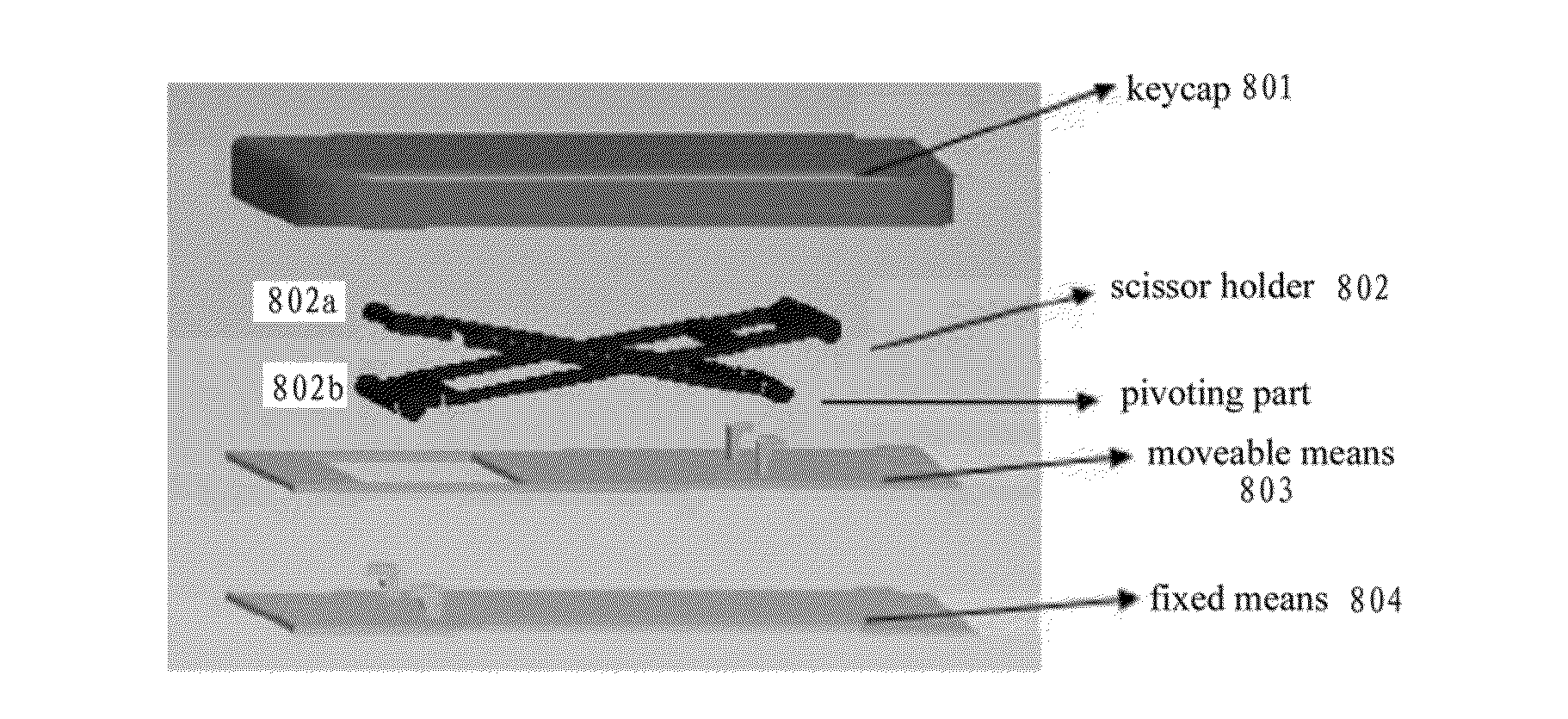
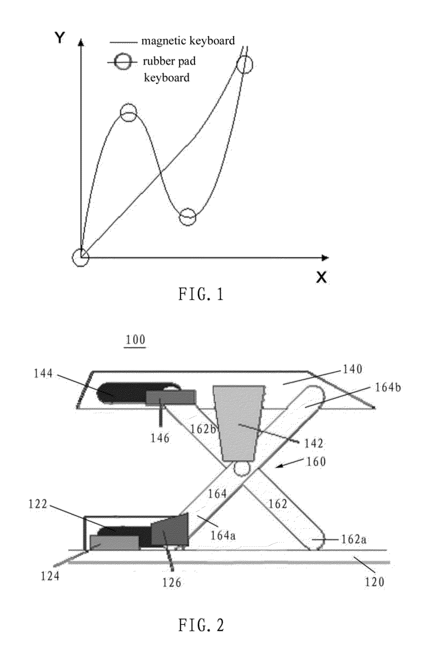
[0048]FIG. 2 shows a keyboard 100 according to an exemplary embodiment of the present invention. As shown in FIG. 2, the keyboard 100 comprises a base plate 120, a keycap 140 and an X-shaped holder 160. The X-shaped holder 160 may also be referred to as scissor legs (hereinafter may also be referred as a scissor holder), and comprises a first lever 162 and a second lever 1...


PUM


Abstract

A keyboard, a driving method and an assembling method for the keyboard, and an electronic device are described. The keyboard includes a base plate, on which a first magnetic member and a second magnetic member are formed; a keycap, disposed above the base plate; and an X-shaped holder disposed between the base plate and the keycap for supporting the keycap, and a third permanent magnet is provided on the sliding end, wherein the keycap is movable between a first position and a second position lower than the first position along a direction substantially perpendicular to the base plate, and wherein the third permanent magnet is in a position substantially opposite to the second magnetic member when the keycap is in the first position, and the third permanent magnet slides to a position substantially opposite to the first magnetic member when the keycap is in the second position.

Description

[0001]This application claims priority to Chinese patent application No. 201110427870.3 filed Dec. 19, 2011 and Chinese patent application No. 201210030586.7 filed Feb. 10, 2012, the entire contents of which is incorporated herein by reference.BACKGROUND OF THE INVENTION[0002]The present invention relates to the field of electronics, and more particularly to a keyboard, a driving method and an assembling method for the keyboard, and an electronic device.[0003]The conventional keyboard comprises keycaps and soft rubber pads supporting the key caps. When a user presses a key, the rubber pad is compressed and the keycap is depressed; when the user releases the key, the rubber pad pushes the keycap back to the initial position.[0004]The soft rubber pad is generally designed to have a tower shape, which is pressed by different distances with different key-press forces. As shown in FIG. 1, the X axis represents for the key-press stroke and the Y axis for the key-press force. At the beginn...

Claims


Application Information

Patent Timeline
Patent Type & Authority Applications(United States)
IPC IPC(8): H01H13/70G06F3/02H01H36/00
CPCH01H13/70H01H36/0073G06F3/02G06F1/1666H01H13/85H01H2221/04G06F1/1618H01H3/125
Inventor GAN, DAYONGJIANG, GUANGJUN
Owner LENOVO (BEIJING) LTD
Why Eureka
Try Eureka