Transmission device, receiving device, transmission method and receiving method

a technology of receiving device and transmission device, which is applied in the direction of signal allocation, transmission path sub-channel allocation, wireless commuication services, etc., can solve the problems of limiting the increase in the number of base stations and the reasonable cost of installation of base stations

Active Publication Date: 2013-06-20
PANASONIC INTELLECTUAL PROPERTY CORP OF AMERICA
View PDF6 Cites 50 Cited by
  • Summary
  • Abstract
  • Description
  • Claims
  • Application Information

AI Technical Summary

Benefits of technology

[0022]The claimed invention can provide a transmission apparatus, a reception apparatus, a transmission method, and a reception method that enable transmission of a series of data while the data is distributed to data resources in N transmission subframes (where N is a natural number greater than or equal to two) when control signals are transmitted in a resource region usable for a control channel or data channel.

Problems solved by technology

The installation of base stations involves reasonable costs, however.
For this reason, there has been a high demand for a technique that provides a communication service using a high-frequency radio band, while limiting an increase in the number of base stations.

Method used


Image

  • Transmission device, receiving device, transmission method and receiving method
  • Transmission device, receiving device, transmission method and receiving method
  • Transmission device, receiving device, transmission method and receiving method

Examples


embodiment 1

[0059](Overview of Communication System)

[0060]A communication system according to Embodiment 1 of the claimed invention includes a transmission apparatus and a reception apparatus. Specifically, in this embodiment of the claimed invention, a description will be provided while the transmission apparatus is referred to as base station 100, and the reception apparatus is referred to as terminal 200. The communication system is an LTE-A system, for example. Base station 100 is an LTE-A base station, and terminal 200 is an LTE-A terminal, for example.

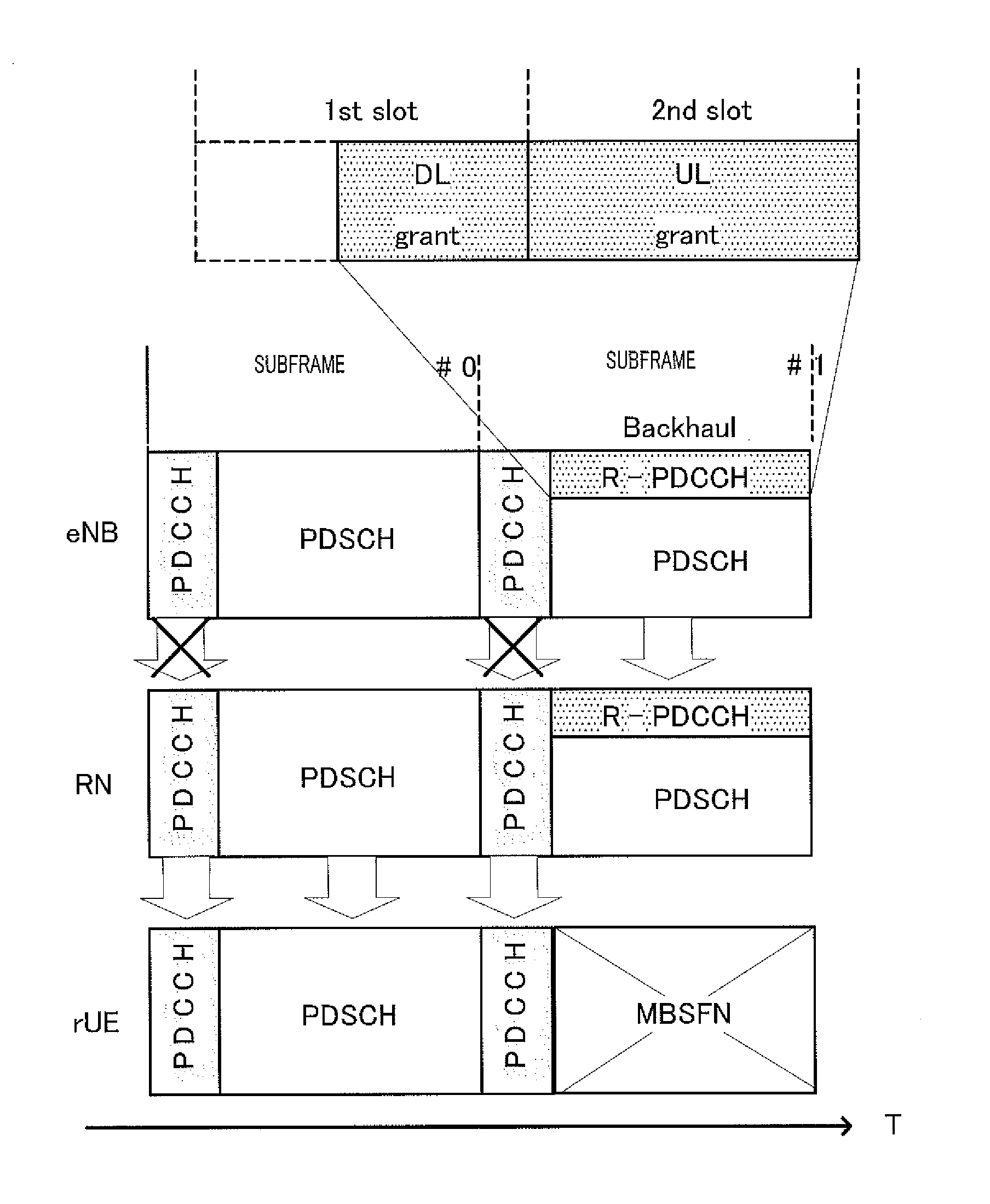
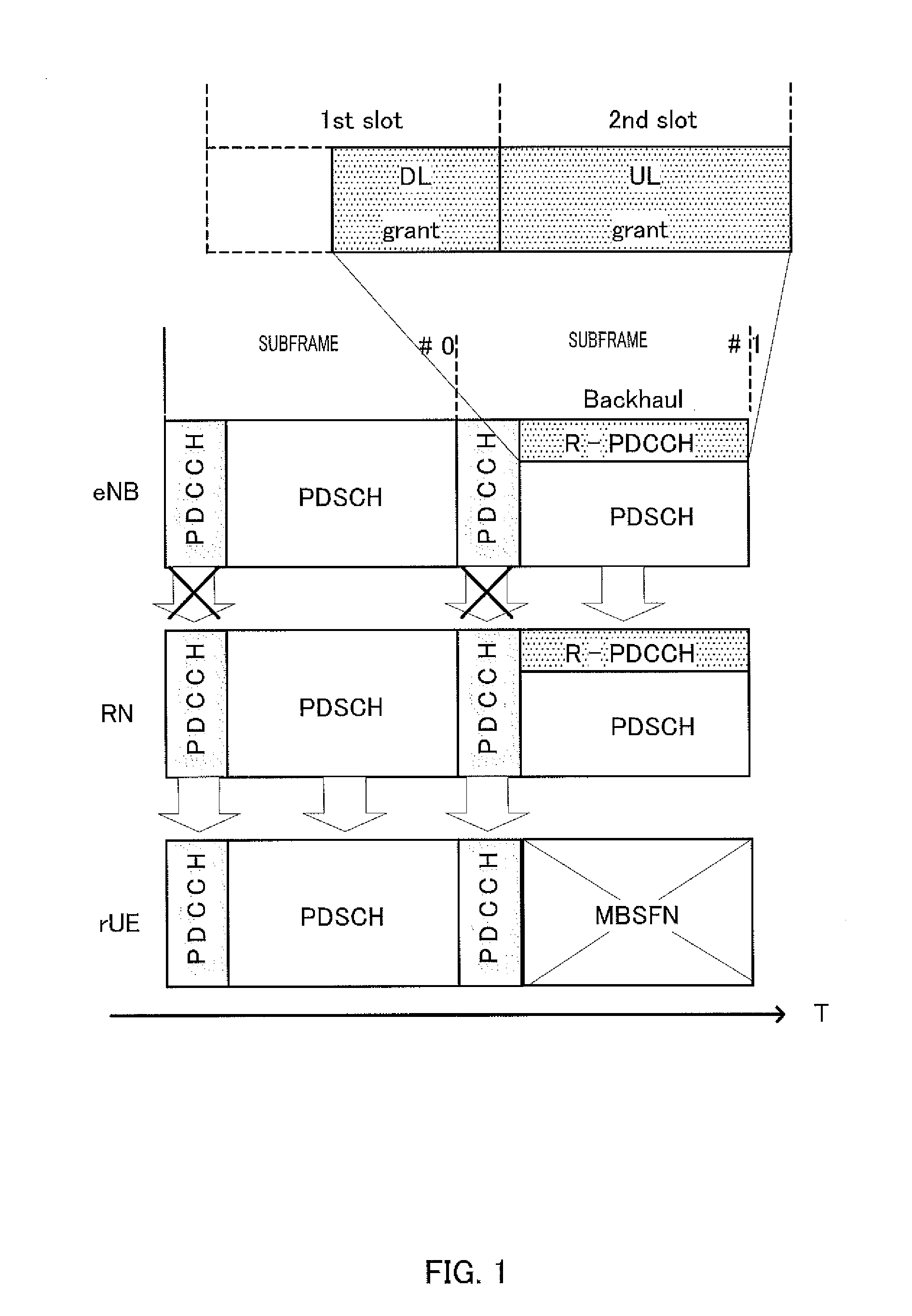
[0061]FIG. 5 illustrates a main configuration of base station 100 according to Embodiment 1 of the claimed invention. Base station 100 transmits control signals for terminal 200 after mapping the control signals to a first resource region usable for a control channel or a data channel (R-PDCCH for a terminal, in this case) or in a second resource region usable for a control channel (a PDCCH, in this case). Base station 100 distributes a seri...

embodiment 2

[0116]Embodiment 2 relates to a variation of the mapping resource pattern corresponding to SPS.

[0117]Specifically, mapping resource pattern 2 according to Embodiment 2 has the following configuration:

[0118](1) mapping resource pattern 2 includes N transmission-scheduled subframes (where N is a natural number greater than or equal to two);

[0119](2) in the first transmission-scheduled subframe of mapping resource pattern 2, region (a), which is described above, is to be a mapping resource for DL grant, but regions (b) and (c) are not to be data resource; and

[0120](3) all regions (a), (b), and (c) are to be data resources in the second and subsequent transmission-scheduled subframes of mapping resource pattern 2.

[0121]Such mapping resource pattern 2 allows reception of data in the second and subsequent transmission-scheduled subframes to be uniform in size, which makes it easier for base station 100 to take the number of resources into consideration for determining an error rate.

embodiment 3

[0122]Embodiment 3 aims at the second object described above. The base station and the terminal according to Embodiment 3 are identical to base station 100 and terminal 200 according to Embodiment 1, respectively, so that a description will be provided with reference to FIGS. 7 and 9.

[0123]In base station 100 according to Embodiment 3, if there are any data signals to be transmitted, transmission controlling section 102 takes, as input, the scheduling identification information outputted from scheduling method determining section 101. Transmission controlling section 102 determines the “mapping resource pattern” of the control signals and the data signals based on the scheduling identification information and outputs the determined information on the mapping resource pattern to signal scheduling section 106.

[0124]The “mapping resource pattern” for the scheduling identification information indicating SPS has the following configuration in particular:

[0125](1) mapping resource pattern...


PUM


Abstract

A base station (100) transmits a DL grant for a terminal (200) by mapping it to an R-PDCCH region, thus transmitting a series of data groups to the terminal (200) by the SPS method. A transmission control unit (102) sets in the R-PDCC H region a control resource region which maps a data resource and the DL grant i n a resource block group common in frames to be transmitted by the SPS method.
A resource region which was defined as a control resource region in a first fram e to be transmitted among a plurality of frames to be transmitted is defined as a d ata resource in a second or subsequent frame to be transmitted.

Description

TECHNICAL FIELD[0001]The claimed invention relates to a transmission apparatus, a reception apparatus, a transmission method, and a reception method.BACKGROUND ART[0002]In recent years, it has become common to transmit large-volume data, such as still image data and moving image data in addition to audio data in cellular mobile communication systems, in response to spread of multimedia information. Active studies associated with techniques for achieving a high transmission rate in a high-frequency radio band has been conducted to achieve large-volume data transmission.[0003]When a high frequency radio band is utilized, however, attenuation increases as the transmission distance increases, although a higher transmission rate can be expected within a short range. Accordingly, the coverage area of a radio communication base station apparatus (hereinafter, abbreviated as “base station”) decreases when a mobile communication system using a high frequency radio band is actually put into o...

Claims


Application Information

Patent Timeline
Patent Type & Authority Applications(United States)
IPC IPC(8): H04W72/04
CPCH04W72/0406H04W84/047H04W72/1294H04L5/0053H04W72/23H04W72/20
Inventor HORIUCHI, AYAKONISHIO, AKIHIKOSAITO, YOSHIKOIMAMURA, DAICHI
Owner PANASONIC INTELLECTUAL PROPERTY CORP OF AMERICA
Why Eureka
Try Eureka