Push broach

a push broach and cutting edge technology, applied in the field of push broaches, can solve the problem of difficulty in machine the plurality of cutting edges of a smaller push broach

Inactive Publication Date: 2013-06-20
JIZHUN PRECISION IND HUIZHOU
View PDF11 Cites 2 Cited by
  • Summary
  • Abstract
  • Description
  • Claims
  • Application Information

AI Technical Summary

Problems solved by technology

However, it is difficult to machine the plurality of cutting edges of a smaller sized push broach.

Method used


Image

  • Push broach
  • Push broach
  • Push broach

Examples


Embodiment Construction

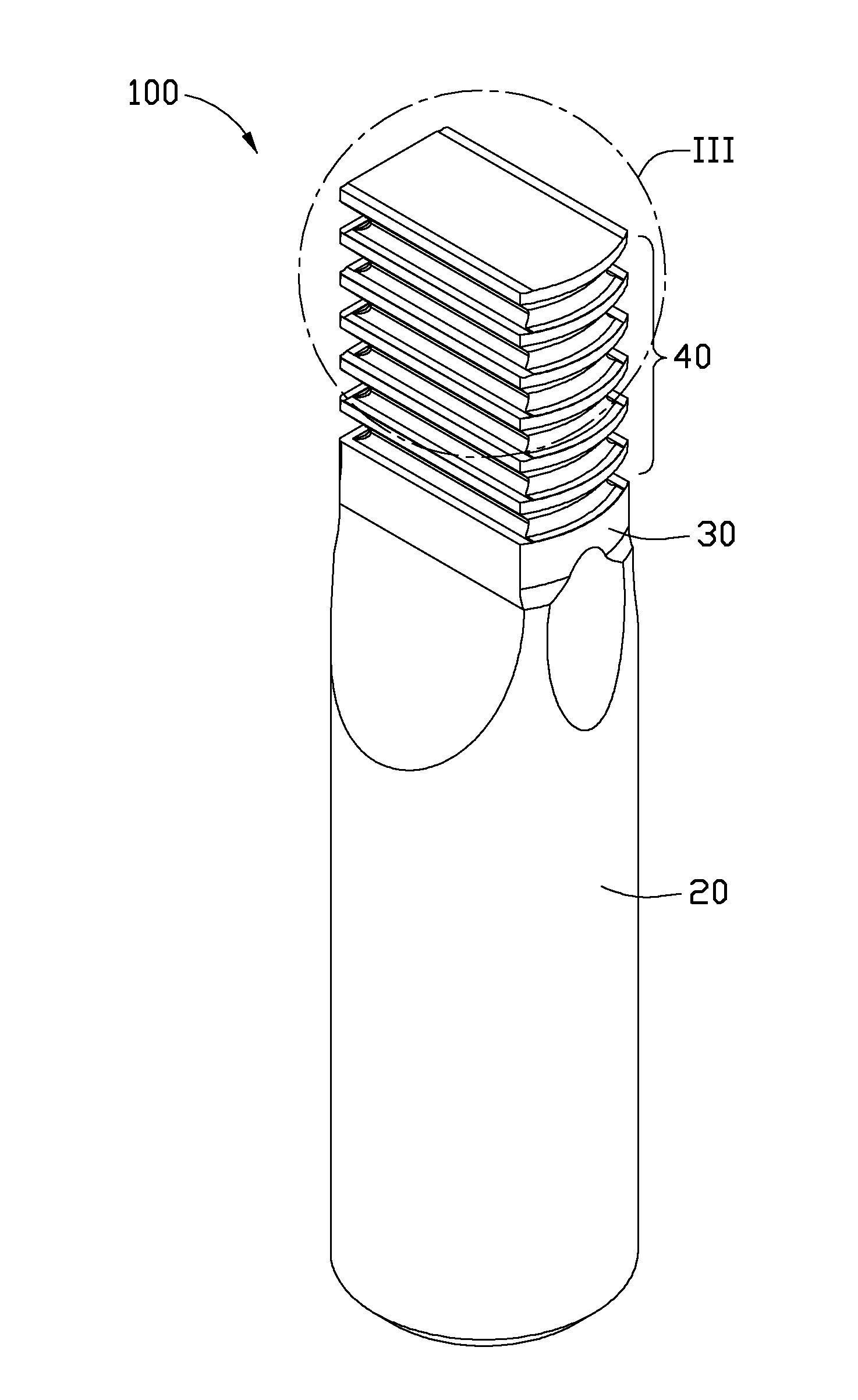
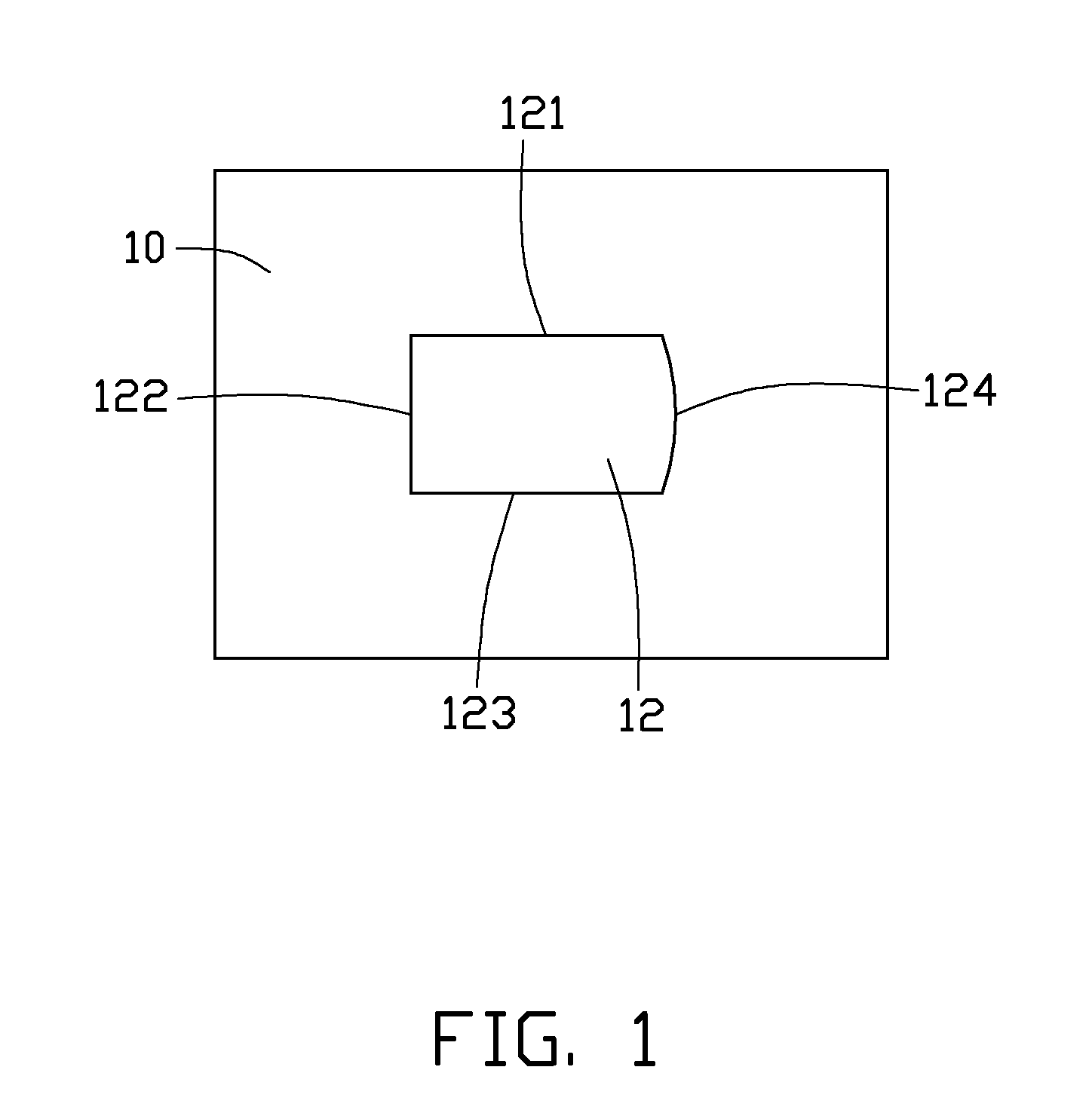
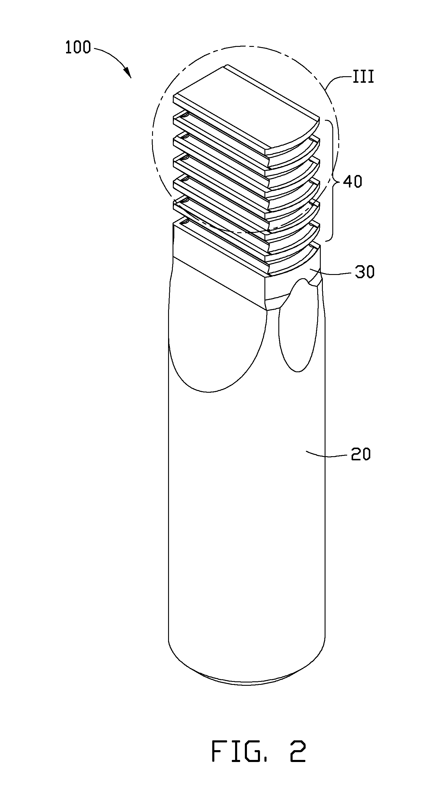
[0010]FIGS. 1 and 2 show an embodiment of a push broach 100 employed to finely machine a pre-machined hole 12 in a metallic workpiece 10. The pre-machined hole 12 is a rough quadrilateral hole with a lateral size smaller than the lateral size of the push broach 100. The push broach 100 finely machines the pre-machined hole 12 and removes a finishing allowance of the pre-machined hole 12, and thereby a metallic workpiece 10 with a hole having a predetermined shape and size, and a smooth appearance is obtained. In an illustrated embodiment, the metallic workpiece 100 is made of aluminum alloy. However, the metallic workpiece 10 can be made of other metallic alloys, such as magnesium alloy, zinc alloy, and stainless steel.

[0011]The pre-machined hole 12 is substantially rectangular, and includes three straight edges 121, 122, 123 and a curved edge 124 connected to each other in an end to end manner. The push broach 100 is substantially a rod shape, and is made of high speed steel. The p...


PUM

PropertyMeasurementUnit
sizesaaaaaaaaaa
front angleaaaaaaaaaa
curved outline shapeaaaaaaaaaa

Abstract

A push broach, for machining a quadrilateral hole or quadrilateral groove, includes a shank portion and a cutting portion connected to the shank portion. The cutting portion includes at least one pair of cutting teeth including a first cutting tooth and a second cutting tooth arranged substantially parallel to the first cutting tooth, the first cutting tooth includes a pair of first cutting edges at two opposite edges thereof, the second cutting tooth includes a pair of cutting edges at two opposite edges thereof, when viewed from an end of the shank portion, each second cutting edge interconnects the pair of first cutting edge, and the pair of the first cutting edges and the pair of second cutting edges cooperatively form a quadrangle enclosing a periphery of the first cutting tooth.

Description

BACKGROUND[0001]1. Technical Field[0002]The present disclosure relates to a cutter, and particularly to a push broach.[0003]2. Description of Related Art[0004]A push broach is used to machine a pre-machined hole on articles. The push broach includes a plurality of cutting teeth uniformly spaced from each other along an axis thereof. Each cutting tooth includes a plurality of cutting edges around a periphery thereof. The plurality of cutting edges of the plurality of cutting teeth is overlapped in an end view. A push broach with a smaller outline size is needed to fabricate a housing of a small electronic device. However, it is difficult to machine the plurality of cutting edges of a smaller sized push broach.[0005]Therefore, there is room for improvement in the art.BRIEF DESCRIPTION OF THE DRAWINGS[0006]The components in the drawings are not necessarily drawn to scale, the emphasis instead placed upon clearly illustrating the principles of the present disclosure. Moreover, in the dr...

Claims


Application Information

Patent Timeline
Patent Type & Authority Applications(United States)
IPC IPC(8): B23D43/02
CPCB23D43/02Y10T407/16Y10T407/1671
Inventor XU, WEN-WU
Owner JIZHUN PRECISION IND HUIZHOU
Why Eureka
Try Eureka