Supercharge Your Innovation With Domain-Expert AI Agents!

Stacked battery

a battery and stacked technology, applied in the field of stacked batteries, can solve the problems of high probability of connection breakage and short circuit, and achieve the effect of reliably preventing short circuit from occurring in the battery

Active Publication Date: 2013-06-20
MAXELL HLDG LTD
View PDF6 Cites 4 Cited by
  • Summary
  • Abstract
  • Description
  • Claims
  • Application Information

AI Technical Summary

Benefits of technology

The present invention provides a stacked battery that prevents short circuits even if there is a break in the connection portion of the electrodes, such as a shock, at the break point. This is achieved by designing the break portion to be reliable for causing breaks and preventing short circuits.

Problems solved by technology

Therefore, a break is highly likely to occur in the connection portion.
If the connection portion is broken, the broken portion is likely to make contact with another electrode causing a short circuit.

Method used


Image

  • Stacked battery
  • Stacked battery
  • Stacked battery

Examples


first embodiment

Advantages of First Embodiment

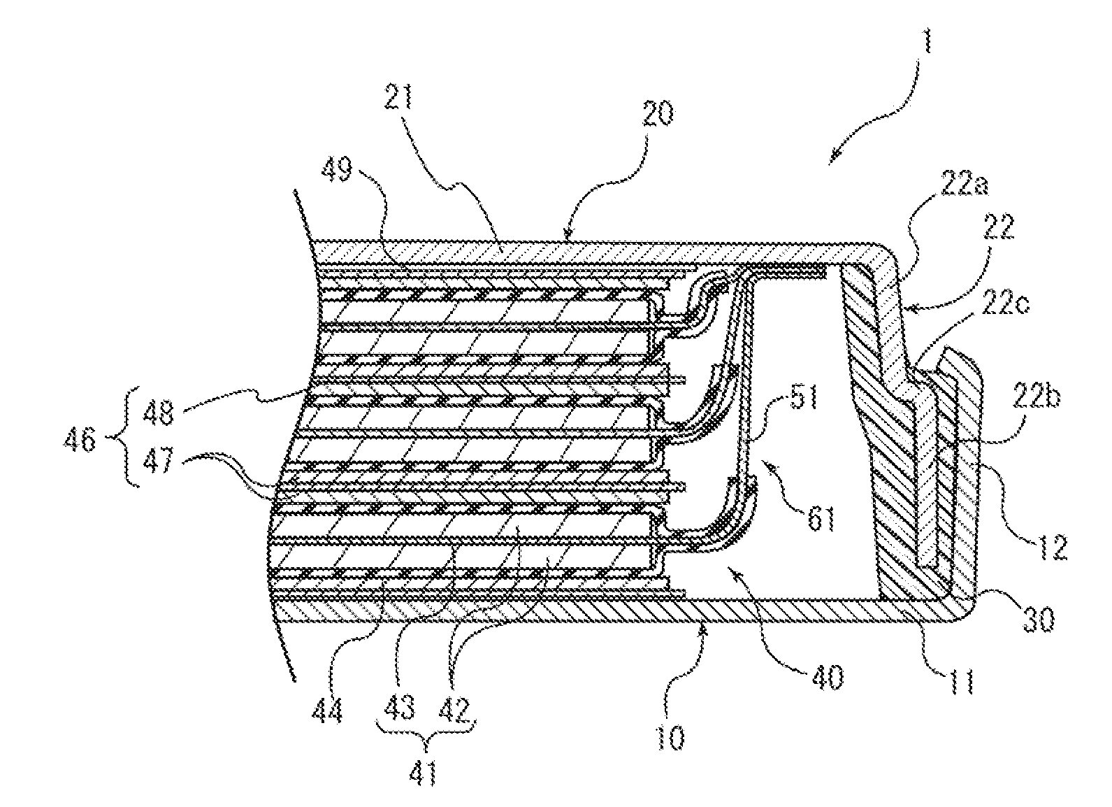
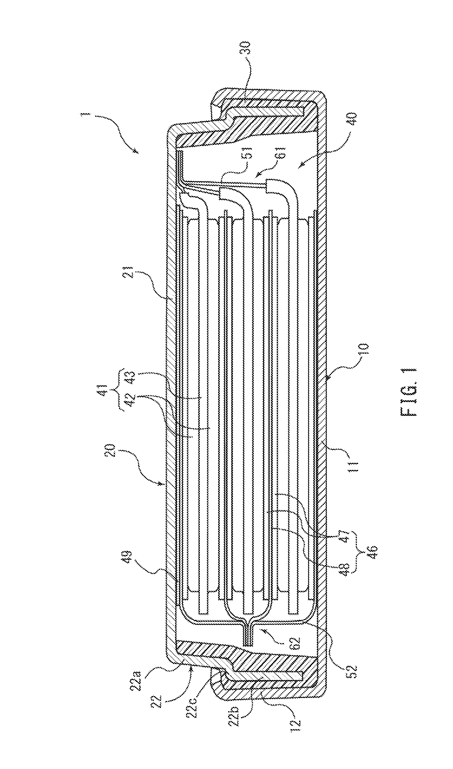
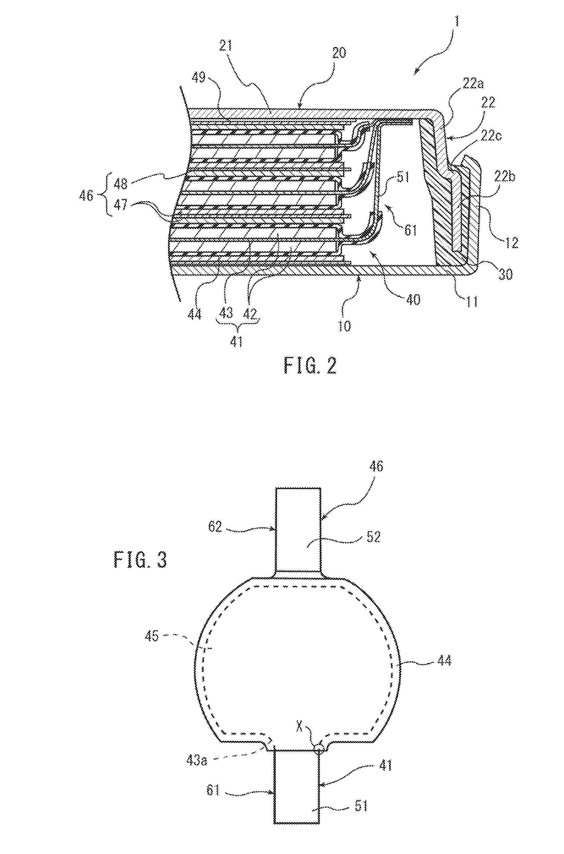
[0056]Thus, according to this embodiment, in the configuration in which the positive and negative electrodes 41 and 46 are alternately placed on top of each other, the R portion 43a is formed at the connection portion of the positive electrode lead 51 to the positive electrode main portion 45 so that the break place X of the positive electrode lead 51 is located outside the negative electrode main portion 50 as viewed from above. As a result, even when a shock is applied to the flat battery 1, so that the positive electrode lead 51 is broken at the break place X, the broken portion does not make contact with the negative electrode 46. As a result, a short circuit can be prevented from occurring between the positive and negative electrodes 41 and 46.

Second Embodiment

[0057]FIG. 7 schematically shows a configuration of a laminate-sheathed battery 100 as a stacked battery according to a second embodiment. FIG. 8 is a cross-sectional view schematically showi...

second embodiment

Advantages of Second Embodiment

[0074]Thus, according to this embodiment, in the laminate-sheathed battery 100, the R portion 111a is provided at the connection portion of the positive electrode lead 133 to the positive electrode main portion 115 so that the break place X of the positive electrode lead 133 is located outside the negative electrode 112 as viewed from above. As a result, even when a shock is applied to the laminate-sheathed battery 100, so that the positive electrode lead 133 is broken at the break place X, the broken portion can be prevented from making contact with the negative electrode 112. As a result, a short circuit can be prevented from occurring between the positive and negative electrodes 111 and 112 due to a break in the positive electrode lead 133.

Other Embodiments

[0075]The embodiments of the present invention described above are only examples for carrying out the present invention. Therefore, the present invention is not limited to the above embodiments. C...


PUM

PropertyMeasurementUnit
diameteraaaaaaaaaa
weightaaaaaaaaaa
polarityaaaaaaaaaa

Abstract

The stacked battery includes a negative electrode (46) and a positive electrode (41). The negative electrode has a negative electrode main portion (50) and a negative electrode lead (52). The positive electrode has a positive electrode main portion (45) and a positive electrode lead (51). In the negative electrode and the positive electrode, the negative electrode main portion and the positive electrode main portion are stacked in a thickness direction with the negative electrode lead and the positive electrode lead extending in different directions as viewed from above. The positive electrode lead is fixed to a positive electrode case. In the positive electrode lead, a break place (X) is provided outside the negative electrode main portion as viewed from above when the negative electrode and the positive electrode are placed on top of each other. The break place (X) is broken when a shock is applied to the electrodes.

Description

TECHNICAL FIELD[0001]The present invention relates to stacked batteries including a stack of first and second electrodes.BACKGROUND ART[0002]A stacked battery including a stack of first and second electrodes is conventionally known. In such a stacked battery, as disclosed, for example, in JP 2009-181898A, positive electrode plates and negative electrode plates are alternately stacked. The stacked battery is connected to external circuitry via collector tabs protruding from the respective positive and negative electrode plates. Also, as disclosed in the above JP2009-181898A, in the stacked battery, an insulating material called a separator is provided between the positive and negative electrode plates. In the stacked battery, the separator prevents a short circuit from occurring between the positive and negative electrode plates.DISCLOSURE OF INVENTION[0003]Incidentally, in the above stacked battery including a stack of electrodes, when a shock is applied due to droppage or the like,...

Claims


Application Information

Patent Timeline
Patent Type & Authority Applications(United States)
IPC IPC(8): H01M2/34H01M6/46H01M2/26H01M50/40H01M50/466H01M50/491H01M50/54
CPCH01M2/266H01M2/347H01M10/0525H01M10/0585Y02E60/122H01M2/18H01M10/0413H01M10/0427H01M10/0436H01M10/0463H01M2/14H01M6/46Y02E60/10H01M50/54H01M50/579Y02P70/50H01M50/40H01M50/491H01M50/466H01M50/531
Inventor KANAI, SUETSUGUFUJIKAWA, KAZUHIRO
Owner MAXELL HLDG LTD
Features
  • R&D
  • Intellectual Property
  • Life Sciences
  • Materials
  • Tech Scout
  • Unparalleled Data Quality
  • Higher Quality Content
  • 60% Fewer Hallucinations
Learn More