Multilayer capacitor

a multi-layer capacitor and capacitor technology, applied in the direction of capacitors, fixed capacitor details, fixed capacitors, etc., can solve the problems of difficult to achieve further reduction in esl, limit of esl reduction in terms of structure, etc., to prevent thermal shock damage, reduce esl, and reduce suction failure

Active Publication Date: 2012-01-31
TDK CORPARATION
View PDF17 Cites 31 Cited by
  • Summary
  • Abstract
  • Description
  • Claims
  • Application Information

AI Technical Summary

Benefits of technology

[0008]Incidentally, in the case of a multilayer capacitor C2 having the terminal electrodes spreading throughout the entire length in the transverse direction of the mount surface in order to provide each of the terminal electrodes 61 with the portion where the electric current flows opposite to the electric current in the internal electrode 60, or in the case of a multilayer capacitor C3 having the terminal electrodes of a fixed terminal width, the reduction effect in ESL can be achieved, but since the multilayer capacitor is miniaturized, for example, so that the longitudinal length of the multilayer capacitor is about 1 mm, a solder bridge B can be made between the terminal electrodes, as shown in FIG. 15, in a process of mounting the terminal electrodes of the multilayer capacitor on a circuit board or the like. Therefore, the inventors discovered that ESL could be reduced while achieving miniaturization, if the terminal electrodes were provided with respective portions in which the electric current flowed opposite to that in the internal electrode, while suppressing occurrence of the solder bridge or the like in the mounting process, thereby accomplishing the present invention.
[0010]In the multilayer capacitor according to the present invention, each second terminal portion has the wide part the width of which is wider than the first lead width of the lead portions in the first internal electrode, and the narrow part the width of which decreases from the wide part toward the second terminal electrode and toward the first or second side face side. The wide part causes the electric current to flow in the lead portion of the first internal electrode in the direction opposite to the electric current flowing in the first terminal electrode, and the narrow part prevents the solder bridge from occurring between the first terminal electrode and the second terminal electrode in the process of mounting the terminal electrodes of the multilayer capacitor on a circuit board or the like. As a result, it becomes feasible to reduce ESL while achieving miniaturization of the multilayer capacitor. Since each terminal electrode is arranged within a certain range without spreading throughout the entire length in the transverse direction of the principal face used in the mounting process, this configuration ensures a space for suction of the multilayer capacitor by a mounter in the mounting process, which reduces suction failure. Furthermore, it also prevents thermal shock damage due to thermal stress difference between the terminal electrodes and the capacitor element body.
[0011]Preferably, the first terminal electrode has a fifth terminal portion arranged on the third side face to connect the first terminal portions to each other, and connected to the first internal electrode. In this case, the first terminal electrode leads the first internal electrode out through the three side faces, so as to reduce the equivalent series resistance (which will be referred to hereinafter as “ESR”).
[0014]Preferably, the second terminal electrode has a seventh terminal portion arranged on the fourth side face to connect the third terminal portions to each other, and connected to the second internal electrode. In this case, the second terminal electrode leads the second internal electrode out through the three side faces, so as to reduce ESR.
[0015]Preferably, the second terminal electrode has eighth terminal portions arranged on the first side face side and on the second side face side, respectively, on the first principal face and connected to the third terminal portions, respectively, and each of the eighth terminal portions includes a wide part a width of which in the direction in which the first and second side faces are opposed, is wider than the second lead width of the lead portions in the second internal electrode, and a narrow part the width of which decreases from the wide part toward the first terminal electrode and toward the first or second side face side on which each eighth terminal portion is arranged. In this case, either of the first and second principal faces can be used as a mount surface, which facilitates the mounting work.

Problems solved by technology

In the multilayer capacitor disclosed in Japanese Patent Application Laid-open No. 2003-051423, however, the degree of reduction in ESL is dependent on the lead width of the internal electrodes and therefore, for achieving reduction in ESL while also achieving miniaturization of the multilayer capacitor, there was a limit of reduction in ESL in terms of the structure and it was difficult to achieve further reduction in ESL.

Method used


Image

  • Multilayer capacitor
  • Multilayer capacitor
  • Multilayer capacitor

Examples


Embodiment Construction

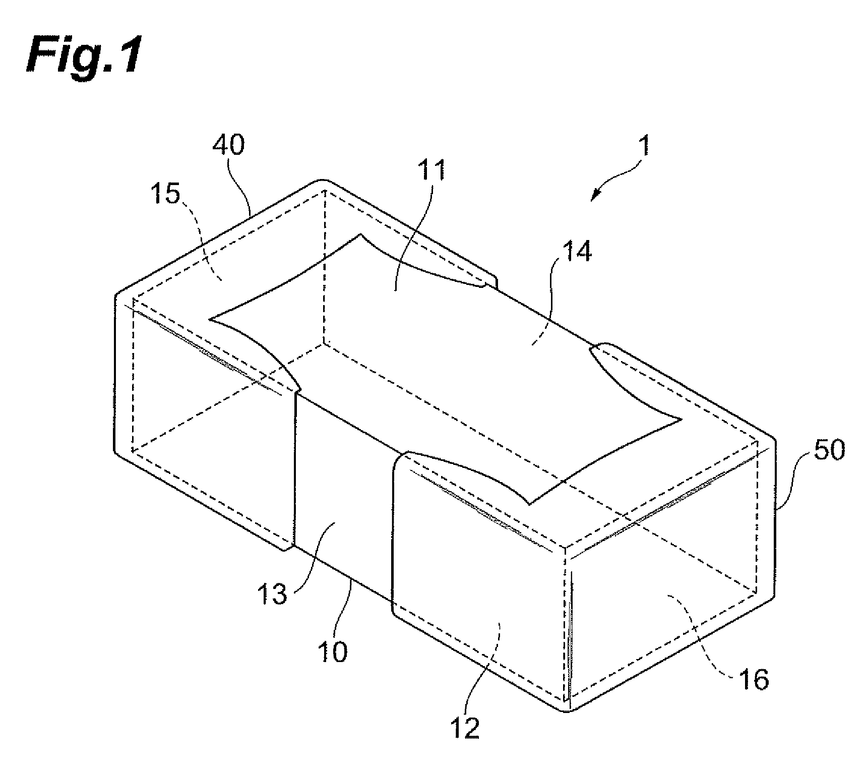
[0032]The preferred embodiments will be described below in detail with reference to the accompanying drawings. In the description the same elements or elements with the same functionality will be denoted by the same reference symbols, without redundant description. A configuration of a multilayer capacitor 1 according to an embodiment of the present invention will be described with reference to FIGS. 1 to 9.

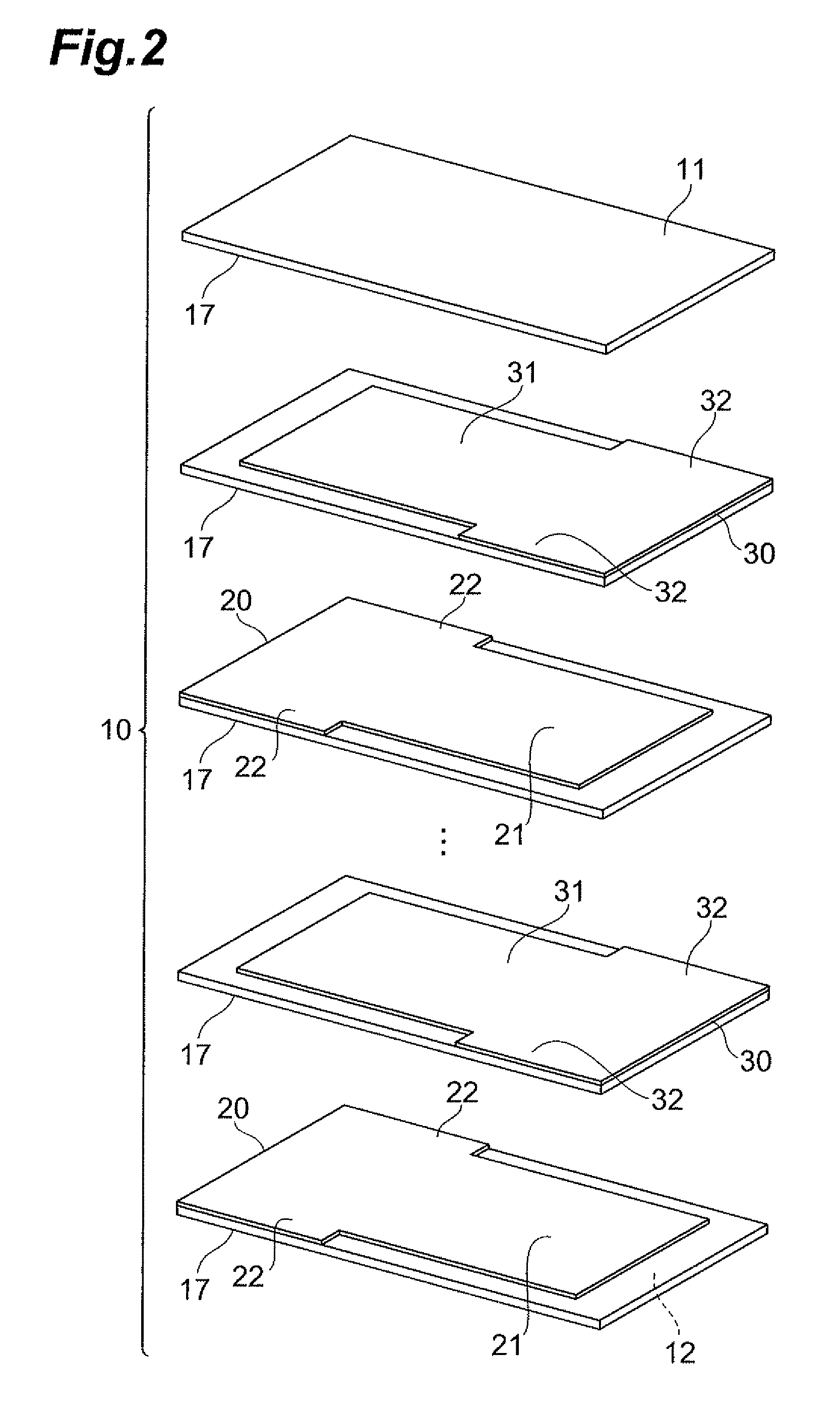
[0033]The multilayer capacitor 1, as shown in FIGS. 1 and 2, has a capacitor element body 10, first internal electrodes 20, second internal electrodes 30, a first terminal electrode 40, and a second terminal electrode 50.

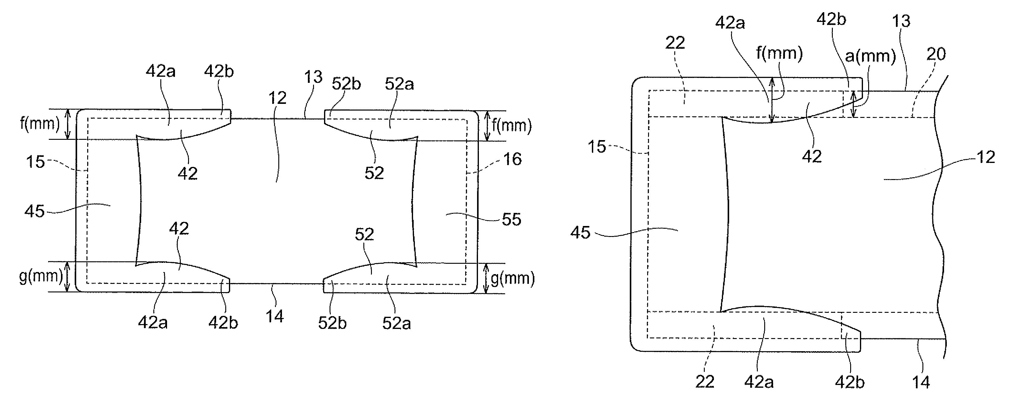
[0034]The capacitor element body 10 is of a nearly rectangular parallelepiped shape and has first and second principal faces 11, 12 of a rectangular shape opposed to each other, first and second side faces 13, 14 opposed to each other and extending in the long-side direction of the first and second principal faces 11, 12 so as to connect the first and second prin...


PUM


Abstract

Each of second terminal portions of a first terminal electrode has a wide part a width of which is larger than a first lead width of lead portions in each first internal electrode, and a narrow part a width of which decreases from the wide part toward the second terminal electrode and toward the first or second side face side. In a multilayer capacitor, the wide part causes an electric current to flow in the lead portions of the first internal electrodes in a direction opposite to that of an electric current flowing in the first terminal electrode, so as to cancel magnetic field thereof each other and thereby reduce ESL, and the narrow part prevents a solder bridge from occurring between the first terminal electrode and the second terminal electrode in a work of mounting the terminal electrodes of the multilayer capacitor on a circuit board or the like.

Description

BACKGROUND OF THE INVENTION[0001]1. Field of the Invention[0002]The present invention relates to a multilayer capacitor.[0003]2. Related Background Art[0004]There is a known multilayer capacitor having a dielectric element body of a nearly rectangular parallelepiped shape in which a plurality of dielectric layers are laminated together, two types of internal electrodes arranged in the dielectric element body, and two terminal electrodes each extending over three side faces of the dielectric element body (e.g., cf. Japanese Patent Application Laid-open No. 2003-051423). In the multilayer capacitor disclosed in this patent document, each of the two types of internal electrodes has a structure in which it is drawn out to the two side faces of the dielectric element body, and thus electric currents flow in opposite directions in the two types of internal electrodes, whereby magnetic fields made thereby cancel each other to reduce the equivalent series inductance (which will be referred ...

Claims


Application Information

Patent Timeline
Patent Type & Authority Patents(United States)
IPC IPC(8): H01G4/228H01G4/005
CPCH01G4/012H01G4/232H01G4/30H01G4/33
Inventor TOGASHI, MASAAKI
Owner TDK CORPARATION
Why Eureka
Try Eureka