Elongate structures and devices and methods for manufacturing same

a technology of elongate structures and devices, applied in the field of elongate structures, can solve the problems of large and detailed machines used in the creation of wooden pallets, affecting the quality of finished products, and occupying space for wooden pallets, etc., and achieves the effect of increasing the beam strength of the elongate structure and increasing the weight of the structur

Inactive Publication Date:
View PDF0 Cites 6 Cited by
  • Summary
  • Abstract
  • Description
  • Claims
  • Application Information

AI Technical Summary

Benefits of technology

[0009]The present invention also provides an elongate structure that includes a hollow outer portion formed of sheet material, a hollow inner portion formed of sheet material, and a separate and distinct U-shaped reinforcement portion formed of sheet material that is disposed within the hollow inner portion. The hollow outer portion includes at least a first outer side surface that defines a first plane, a second outer side surface that defines a second plane, and a third outer side surface that defines a third plane. The first plane intersects with the second plane at a first dihedral angle and the second plane intersects with the third plane at a second dihedral angle. Further, the third plane intersects with the first plane at a third dihedral angle. The sum of the first dihedral angle, the second dihedral angle, and the third dihedral angle is about 180°. The hollow inner portion is disposed within the hollow outer portion. The hollow inner portion contacts a first inner side of the hollow outer portion opposite the first outer side surface. A second inner side surface of the hollow outer portion is opposite the second outer side surface. A third inner side surface of the hollow outer portion is opposite the third outer side surface. The hollow inner portion includes at least a first panel that extends between the first inner side of the hollow outer portion and the second inner side of the hollow outer portion so as to define a first hollow inner triangular channel. A second panel extends between the second inner side of the hollow outer portion and the third inner side of the hollow outer portion so as to define a second hollow inner triangular channel. The U-shaped reinforcement portion, which is disposed within the hollow inner portion, increases the beam strength of the elongate structure without substantially increasing the weight of the structure.

Problems solved by technology

Furthermore, the creation of wooden pallets typically requires large and detailed machines that are kept offsite from the facility that is loading the packages onto the pallets.
Wooden pallets take up room, are easily broken and thus are frequently in need of repair.

Method used


Image

  • Elongate structures and devices and methods for manufacturing same
  • Elongate structures and devices and methods for manufacturing same
  • Elongate structures and devices and methods for manufacturing same

Examples


third embodiment

[0047]FIG. 6 shows the elongate structure 10 of the third embodiment in a fully assembled state. To close the end flaps, end flap 95 is folded over first, then end flap 93 is folded over onto end flap 95, and finally, end flap 91 is folded over onto end flap 93. Similarly, on the opposite side of the elongate structure 10, end flap 96 is folded over first, then end flap 94 is folded over onto end flap 96, and finally, end flap 92 is folded over onto end flap 94. The end flaps are then secured using adhesive, tape or fasteners.

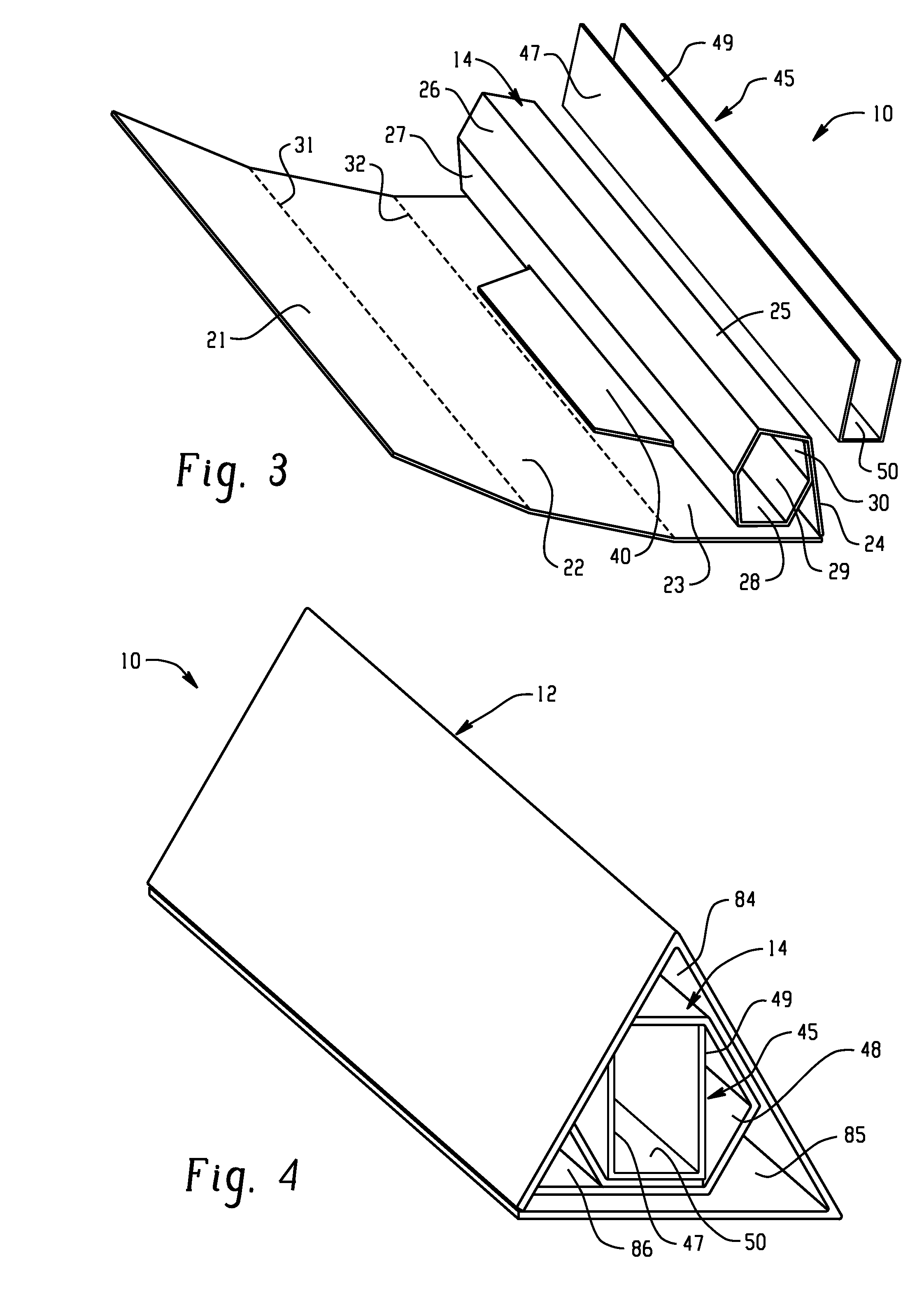
[0048]Referring again to FIG. 7, which shows another exemplary embodiment of the elongate structure 10. This embodiment is similar to the embodiment described above with the exception that the present embodiment has a hollow outer portion 12 that defines the shape of a trapezoid and more specifically, an isosceles trapezoid. An isosceles trapezoid is a trapezoid where the two non-parallel sides and base angles are equal. The hollow outer portion 12 includes a l...

fifth embodiment

[0049]Further, the elongate structure 10 shown in FIG. 7 possesses similar characteristics and features as the elongate structure 10 previously described and shown in FIGS. 1-4. For example, the elongate structure 10 in FIG. 7 includes the reinforcement member 45. In addition, because the small parallel side 51A is parallel to the large parallel outer side 51, the elongate structure according to the invention can be used in applications other than shipping containers. For example, FIGS. 8-10 show another application for the elongate structure 10 disclosed herein. Specifically, FIGS. 8-11 illustrate several embodiments of a pallet incorporating the elongate structure 10, which serve as pallet runners for the pallet.

[0050]FIG. 8 shows an embodiment of a pallet 100 incorporating the elongate structure 10 according to an embodiment of the invention. The pallet 100 is formed by securing at least two, and preferably three or more, elongate structures 10 to a sheet or deck 102 of material ...


PUM


Abstract

A device for wrapping a substantially flat piece of sheet material with a plurality of creases that define fold lines that when folded, forms an elongate structure that includes a hollow outer portion and a hollow inner portion disposed within the hollow outer portion. The device includes a mandrel, a gripper blade that releasably secures the sheet material to the mandrel, a motor that rotates the mandrel when the sheet material is secured to the mandrel, and a compressive member that releasably presses the first outer side surface of the hollow outer portion of the elongate structure against the inner portion of the elongate structure after the sheet material has been wrapped about the mandrel. The device can also include a controller that is operably associated with the motor and the compressive member.

Description

CROSS-REFERENCE TO RELATED APPLICATIONS[0001]This application is a continuation-in-part of PCT / US2011 / 039370, filed Jun. 7, 2011, which claims priority to U.S. App. Ser. No. 61 / 373,481, filed Aug. 13, 2010, and also a continuation-in-part of U.S. application Ser. No. 13 / 071,157, filed Mar. 24, 2011, which is a continuation of PCT / US2010 / 058559, filed Dec. 1, 2010, which claims priority to U.S. App. Ser. No. 61 / 266,422, filed Dec. 3, 2009 and U.S. App. Ser. No. 61 / 373,481, filed Aug. 13, 2010.BACKGROUND OF INVENTION[0002]1. Field of the Invention[0003]The present invention relates to an elongate structure with a reinforcement member and also to a device for folding a piece of sheet material into an elongate structure. The present invention also relates to a method for manufacturing elongate structures.[0004]2. Description of Related Art[0005]Due to increased fuel costs, there is renewed interest in ways to save energy during the transportation of goods. One way to accomplish this tas...

Claims


Application Information

Patent Timeline
Patent Type & Authority Applications(United States)
IPC IPC(8): B31F1/00
CPCB31F1/0009B31D5/0086B65D19/0026B65D2519/00019B65D2519/00054B65D2519/00069B65D2519/00089B65D2519/00104B65D2519/00124B65D2519/00139B65D2519/00273B65D2519/00288B65D2519/00318B65D2519/00323B65D2519/00333B65D2519/00343B65D2519/00378B65D2519/00432B65D2519/00447B65D2519/00562B65D2519/00572B31C1/00B65D19/0012
Inventor ERDIE, JASON S.
Why Eureka
Try Eureka