
Air Conditioner Self-Charging And Charge Monitoring System

a self-charging and charge monitoring technology, applied in refrigeration and liquidation, refrigeration machines, lighting and heating apparatus, etc., can solve problems such as premature compressor failure, damage to motors and mechanical components, and reduce system energy efficiency

Active Publication Date: 2013-06-27
CARRIER CORP
View PDF14 Cites 28 Cited by
  • Summary
  • Abstract
  • Description
  • Claims
  • Application Information

AI Technical Summary

Benefits of technology

The invention provides methods for determining the level of refrigerant charge in a vapor compression system by using information such as compressor torque or current. The methods involve controlling system variables, measuring the discharge pressure and degree of refrigerant subcooling, and comparing them with target values. The level of refrigerant charge can be outputted in real-time for the duration of system operation. These methods help to optimize the performance of vapor compression systems and ensure safe and reliable operation.

Problems solved by technology

Improper charge level, either in deficit or in excess, can cause a reduced system energy efficiency and premature compressor failure in some cases.
An excess charge in the system results in compressor flooding which, in turn, may be damaging to the motor and mechanical components.
Inadequate or a deficit refrigerant charge can lead to reduced system capacity, thus reducing system efficiency.
A deficit charge also causes an increase in refrigerant temperature entering the compressor, which may cause thermal overload of the compressor.
Thermal overload of the compressor can cause degradation of the motor winding insulation, thereby bringing about premature motor failure.
Thermal overload may also cause overheating and damage the pumping elements.
As operating conditions may vary widely from day to day, the particular amount of subcooling measured by the field service technician at any given time may not truly reflect the amount of subcooling present during “normal” operation of the system.
As a result, this charging procedure is also an empirical, time-consuming, and a trial-and-error process subject to human error.

Method used


Image

  • Air Conditioner Self-Charging And Charge Monitoring System
  • Air Conditioner Self-Charging And Charge Monitoring System
  • Air Conditioner Self-Charging And Charge Monitoring System

Examples


Embodiment Construction

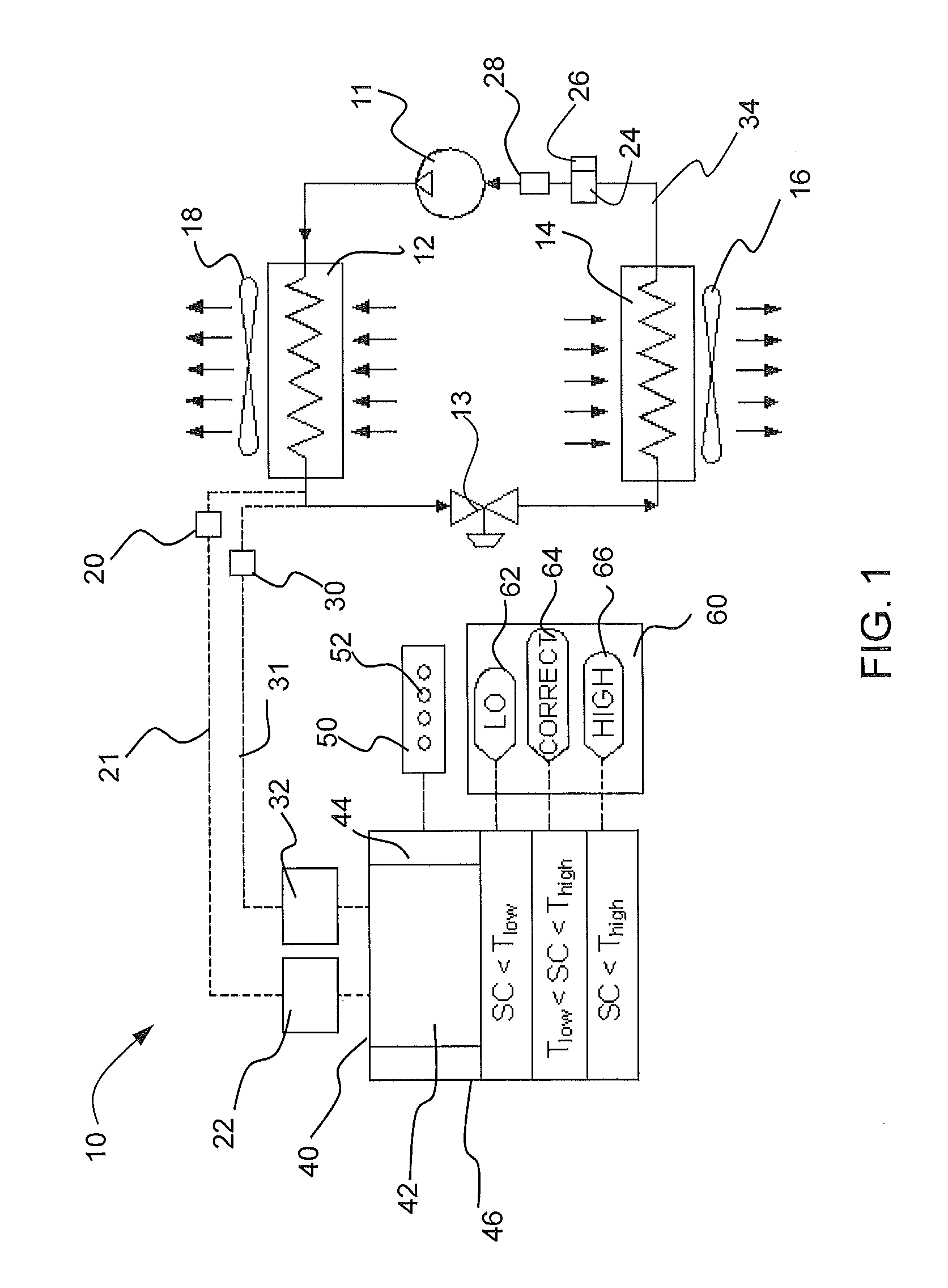
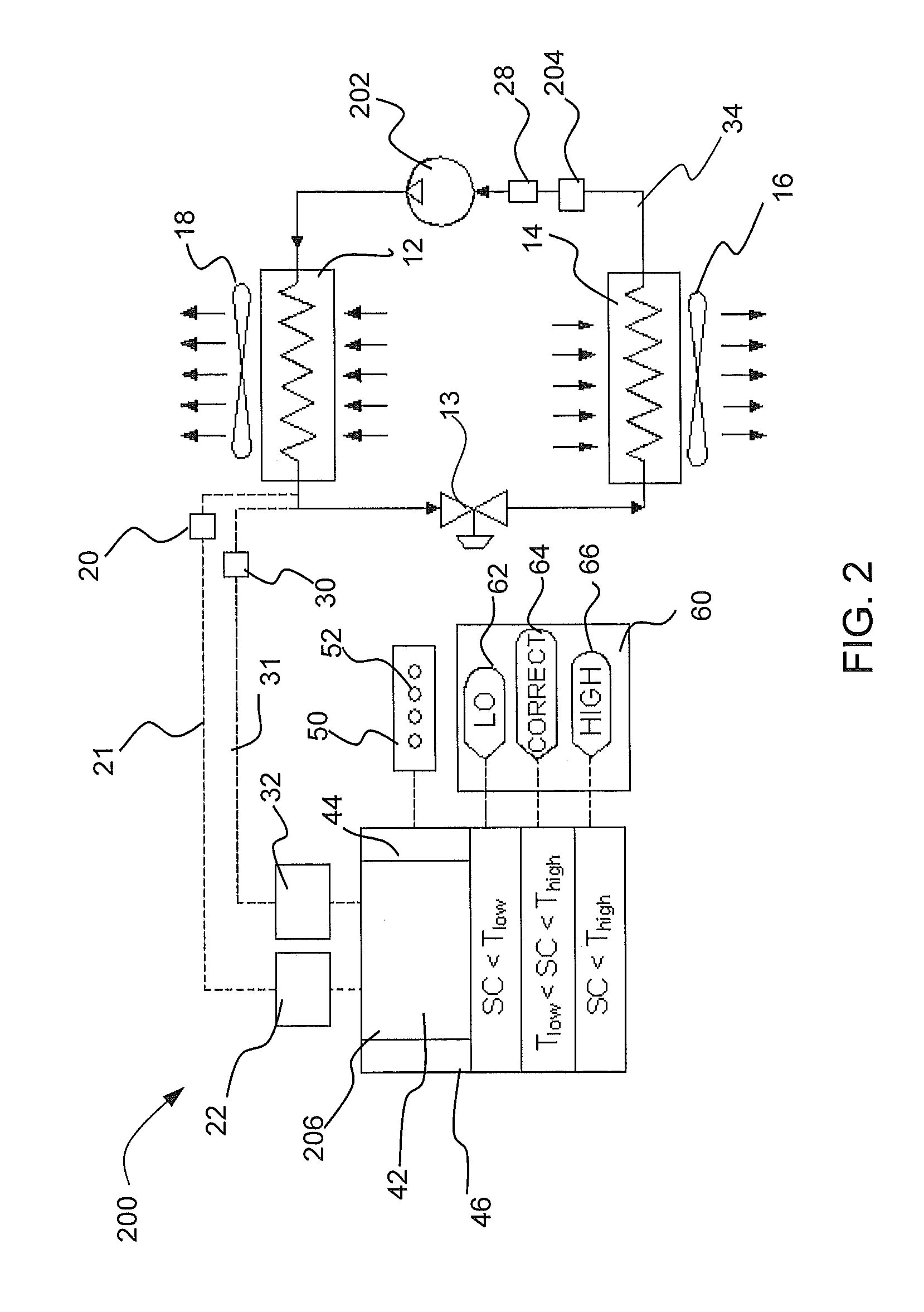
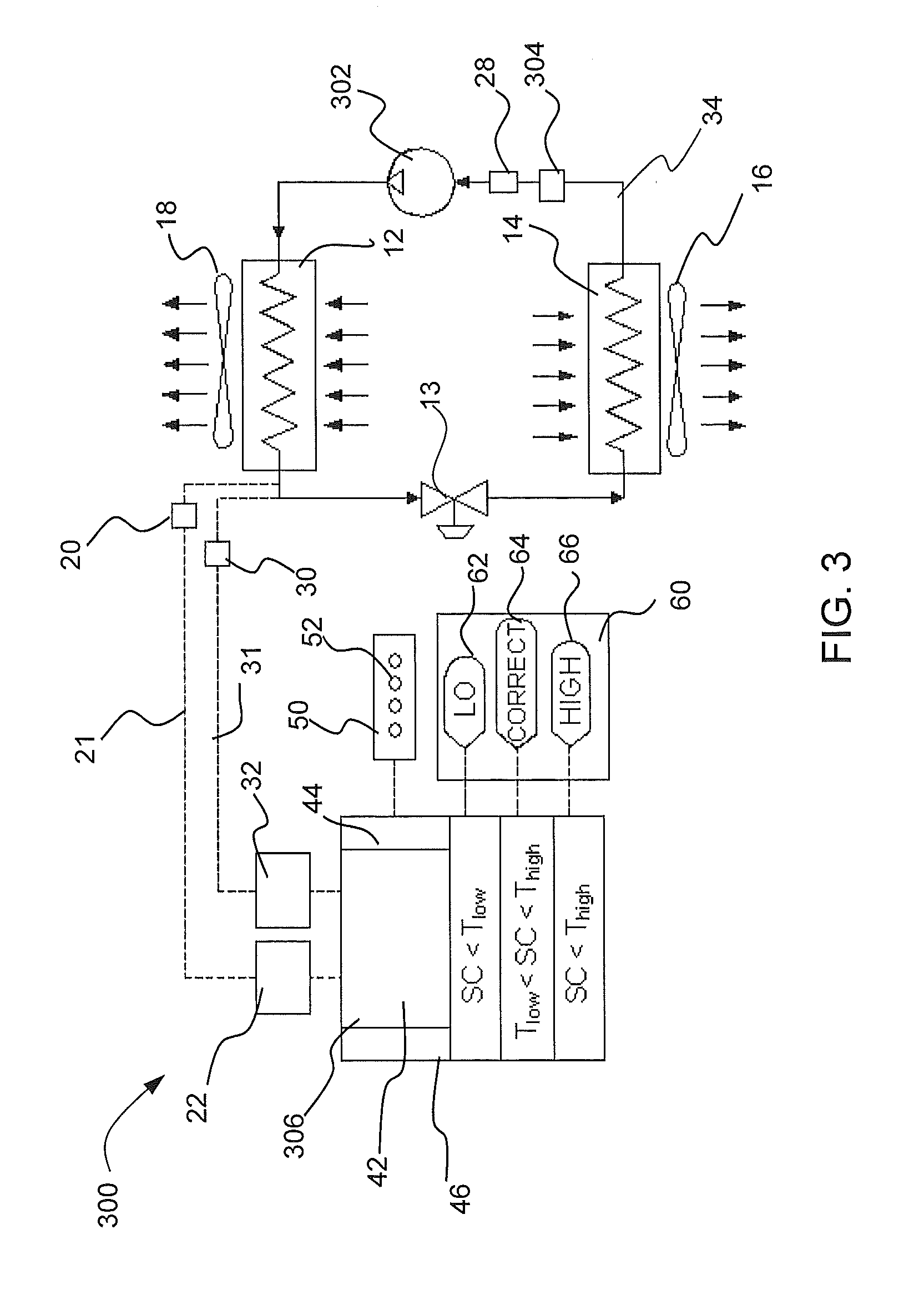
[0014]Embodiments of a refrigerant vapor compression air conditioning system having self-charging and charge monitoring modes includes a controller operably connected to the system in order to facilitate refrigerant charging in a “self-charging” mode and to continuously monitor the refrigerant charge in a “charge monitoring” mode. In embodiments, the refrigerant subcooling is utilized for the self-charging and charge monitoring modes for the system utilizing either a variable speed compressor or a single speed non-variable speed compressor. In an embodiment, refrigerant subcooling is utilized to monitor the charge utilizing liquid line subcooling or system subcooling. Additional embodiments utilize compressor torque to predict discharge pressure using a map to the discharge pressure and subsequently to the saturated refrigerant temperature and liquid line temperature to obtain system subcooling or alternately from actual liquid line pressure or discharge line pressure from a dedicat...


PUM


Abstract

A method for determining a level of refrigerant charge in a vapor compression system having a compressor, a condenser, an expansion device and an evaporator operatively connected in serial relationship in a refrigerant flow circuit having a refrigerant, includes receiving information indicative of at least one of a compressor torque or compressor current; and determining whether the refrigerant charge is within a defined tolerance or whether the refrigerant is to be added or recovered in response to the receiving of the information.

Description

CROSS REFERENCE TO RELATED APPLICATIONS[0001]This applications claims the benefit of U.S. provisional patent application Ser. No. 61 / 580,373 filed Dec. 27, 2011, the entire contents of which are incorporated herein by reference in their entirety.FIELD OF INVENTION[0002]This invention relates generally to refrigerant vapor compression systems for residential or light commercial air conditioning applications and, more particularly, to a method and system for self-charging and monitoring the refrigerant charge in such system.DESCRIPTION OF RELATED ART[0003]Maintaining a proper refrigerant charge level is essential to the safe and efficient operation of an air conditioning system. Improper charge level, either in deficit or in excess, can cause a reduced system energy efficiency and premature compressor failure in some cases. An excess charge in the system results in compressor flooding which, in turn, may be damaging to the motor and mechanical components. Inadequate or a deficit refri...

Claims


Application Information

Patent Timeline
Patent Type & Authority Applications(United States)
IPC IPC(8): F25B45/00
CPCF25B45/00F25B2345/001F25B2345/002F25B2500/19F25B2700/21163F25B2700/151F25B2700/1931F25B2700/1933F25B2700/195F25B2700/04
Inventor SCHUSTER, DON A.ADEPETU, ADEYEMI A.DAS, SATHISH R.SHAH, RAJENDRA K.
Owner CARRIER CORP
Learn More