
Warming oven having light reflection effect

a technology of light reflection and heating oven, which is applied in the direction of domestic stoves or ranges, combustion types, gaseous heating fuel, etc., can solve the problems of limited illumination effect, and achieve the effect of enhancing the illumination

Inactive Publication Date: 2013-06-27
ALLGREEN DESIGNS
View PDF1 Cites 8 Cited by
  • Summary
  • Abstract
  • Description
  • Claims
  • Application Information

AI Technical Summary

Benefits of technology

The patent is about a warming oven that has light reflecting features to improve its lighting performance. The oven has a base, a heating unit, a heat conducting unit, and a reflective shield. The heating unit is placed inside the base, while the heat conducting unit has a positioning plate, a top plate, and a quartz glass tube. Connecting rods are placed around the positioning plate and the top plate. The reflective shield has vent holes and a bottom cover that covers the top end of the heat conducting unit. The bottom cover also has a curved outer mirror surface that reflects light from a fire flame produced by the heating unit, giving the oven an illumination effect. In summary, this patent describes a warm oven that uses light reflection to improve its lighting performance.

Problems solved by technology

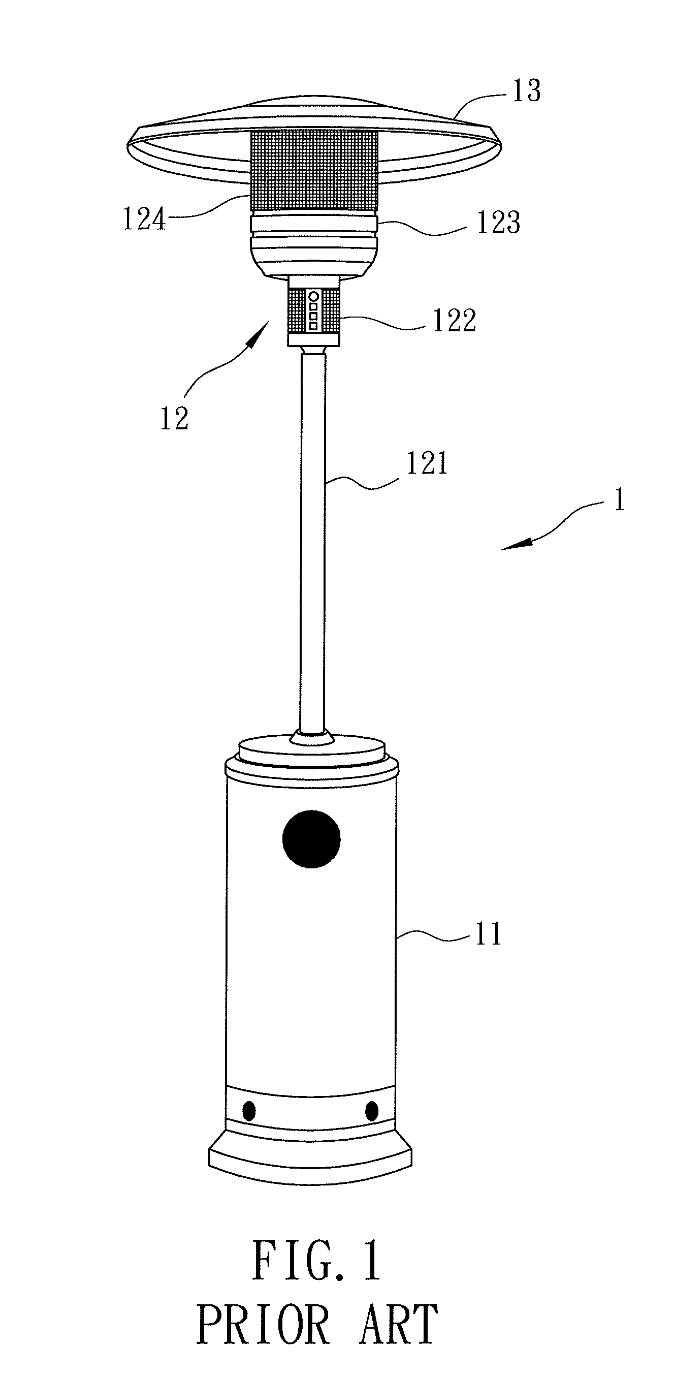
However, due to the presence of the top cap 13, the illumination effect is limited.

Method used


Image

  • Warming oven having light reflection effect
  • Warming oven having light reflection effect
  • Warming oven having light reflection effect

Examples


Embodiment Construction

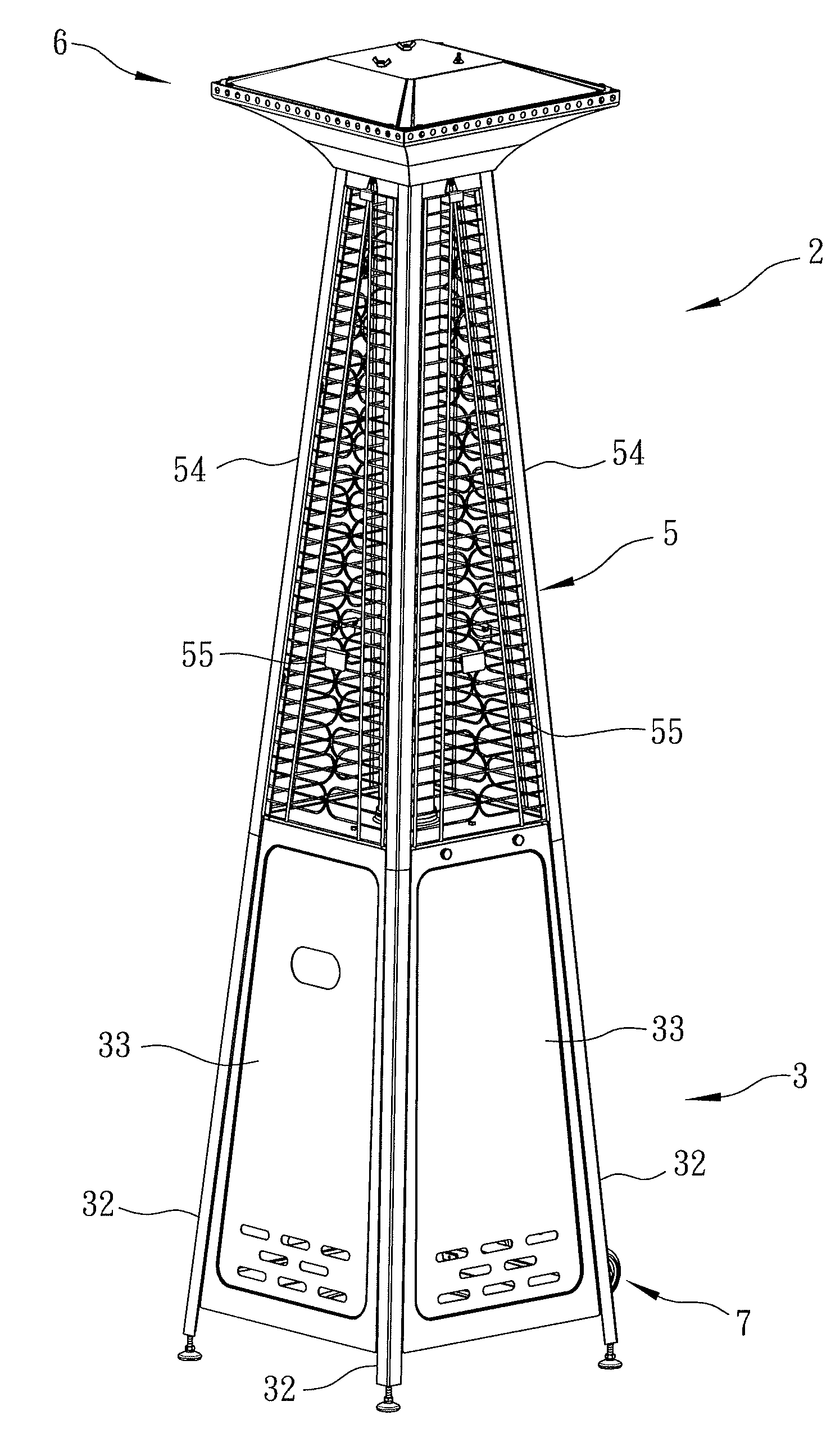
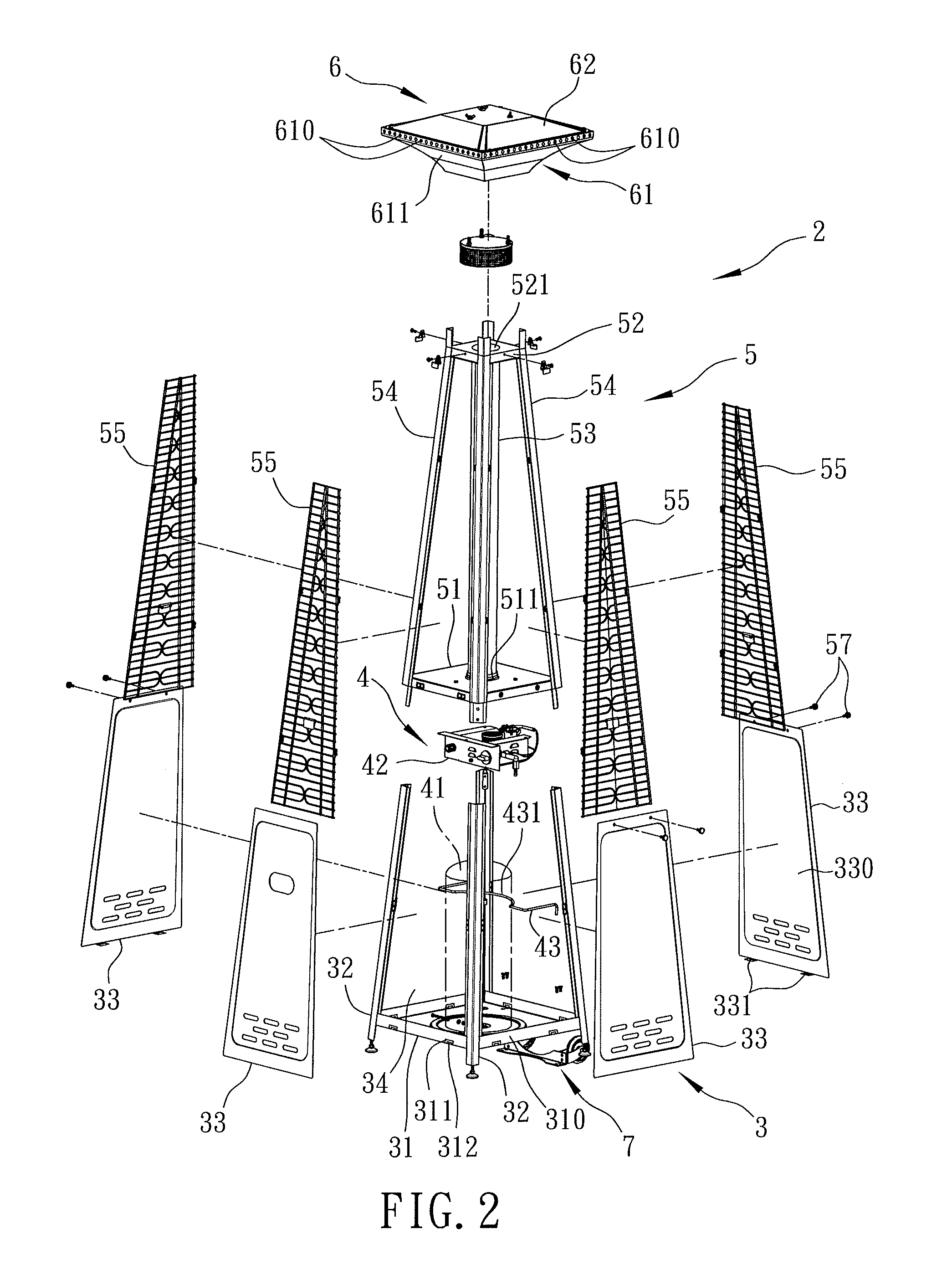
[0016]Referring to FIGS. 2 and 3, the preferred embodiment of a warming oven 2 according to this invention includes a base 3, a heating unit 4, a heat conducting unit 5, a reflective shield 6, and a roller unit 7 disposed on a periphery of the base 3.

[0017]The base 3 includes a supporting plate 31, a plurality of upright supporting rods 32 disposed around and connected to the supporting plate 31, and a plurality of stop plates 33 each connected between two adjacent ones of the supporting rods 32. The supporting plate 31 cooperates with the supporting rods 32 and the stop plates 33 to define an accommodating space 34 above the supporting plate 31 and among the supporting rods 32 and the stop plates 33. In this embodiment, the supporting plate 31 is square, and has four upright side plate portions 310 disposed respectively at four sides thereof. Each of the sideplate portions 310 is formed with an inverted U-shaped slot 311 therethrough that has a horizontal slot section and two uprig...


PUM


Abstract

A warming oven includes a base, a heating unit, a heat conducting unit, and a reflective shield. The base has an accommodating space. The heating unit is disposed within the accommodating space. The heat conducting unit includes a positioning plate, a top plate spaced apart from the positioning plate, a quartz glass tube inserted into the positioning plate and the top plate, and a plurality of upright connecting rods disposed around the positioning plate and the top plate. The reflective shield is formed with a plurality of vent holes, and includes a bottom cover that covers a top end of the heat conducting unit and that has a vertically curved outer mirror surface for reflecting light from a fire flame produced by the heating unit, thereby providing an illumination effect.

Description

CROSS-REFERENCE TO RELATED APPLICATION[0001]This application claims priority of Taiwanese Application No. 100224155, filed on Dec. 21, 2011.BACKGROUND OF THE INVENTION[0002]1. Field of the Invention[0003]This invention relates to a heating device, and more particularly to a heating device having light reflection effect.[0004]2. Description of the Related Art[0005]Referring to FIG. 1, a conventional outdoor warming oven 1 disclosed in Taiwanese Utility Model Patent Publication No. 392837 includes a barrel receiving cylinder 11 for accommodating a gas barrel (not shown) therein, a combustion unit 12 disposed fixedly above the barrel receiving cylinder 11, and a top cap 13 for covering the combustion unit 12. The combustion unit 12 includes a supporting post 121 fixed on and above the barrel receiving cylinder 11, an ignition switch 122 disposed on the supporting post 121, a burner 123 controlled by the ignition switch 122 to produce a fire flame, and a shield 123 surrounding the burne...

Claims


Application Information

Patent Timeline
Patent Type & Authority Applications(United States)
IPC IPC(8): F24H3/00F24H9/18
CPCF24C3/14F24C15/22F24C15/007F24C3/002F24C15/08F23D2212/00F23D14/12F23C3/002F24C15/06F23D2213/00F23D14/148F23D14/151F24C3/022
Inventor YEN, WEN-CHANG
Owner ALLGREEN DESIGNS
Learn More