Roof integrated solar module assembly

Inactive Publication Date: 2013-06-27
SOLOPOWER
View PDF0 Cites 53 Cited by
  • Summary
  • Abstract
  • Description
  • Claims
  • Application Information

AI Technical Summary

Benefits of technology

[0013]The aforementioned needs are satisfied by embodiments of the present invention which, in a solar module assembly comprises a solar module having a convexly curved or angled plate like body defined by a curved or angled transparent top layer of the solar module disposed over a curved or angled bottom layer of the solar module, wherein a plurality of solar cells are disposed between the curved or angled transparent top layer and the curved or angled bottom layer such that light receiving sides of the solar cells face the curved or angled transparent top layer; and a curved or angled support to retain the curved or angled solar module, the curved or angled support including a curved or angled support top surface that substantially contacts and conforms to the curved or angled bottom layer of the solar module.
[0014]The solar module may also comprise a plurality of solar cells and a solar module body having a top transparent layer and a bottom layer and first and second lateral edges, wherein the transparent layer and bottom layer define a space that receives the plurality of solar cells and wherein a portion of the top transparent layer is elevated with respect to the first and second lateral edges to facilitate snow and water sliding off of the top transparent layer towards the first and second lateral edges.
[0015]In one aspect, the aforementioned needs are satisfied by a method of installing a rooftop solar system on a roofing surface comprising affixing an array of base elements including a plurality of fastening members to the roofing surface engaging feet of a module support with the plurality of fastening members of base elements so as to fasten the module support to the base elements on the roofing surface, wherein the module support having a top surface that is convexly curved or angled along a longitudinal axis of the top surface, and wherein the top surface includes a major surface portion that is generally separated from a minor surface portion along the longitudinal axis of the top surface. In this aspect, the method also comprises attaching a flexible solar module onto the top surface of the module support, the flexible module having a plate like body defined by a top transparent layer disposed over a bottom layer, wherein the bottom layer of the solar module is in physical contact with and is substantially supported by the top surface of the module support by covering the major surface and partially covering the minor surface of the top surface so as to leave an exposed access space on the minor surface.
[0016]In another aspect the aforementioned needs are satisfied by a solar module assembly installed on an application surface, comprising at least two base elements affixed to the application surface, the base elements including a bottom surface and an upper surface, wherein the upper surface includes a

Problems solved by technology

Although the added thickness improves the strength of the flat glass sheet, the weight associated with the increased thickness of the glass has its own drawbacks.
One of the drawbacks is the high cost of installing such heavy panels on the rooftops, and possibl

Method used


Image

  • Roof integrated solar module assembly
  • Roof integrated solar module assembly
  • Roof integrated solar module assembly

Examples


Embodiment Construction

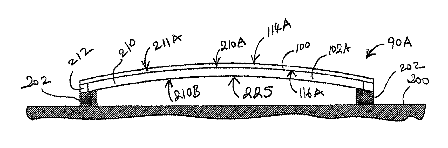
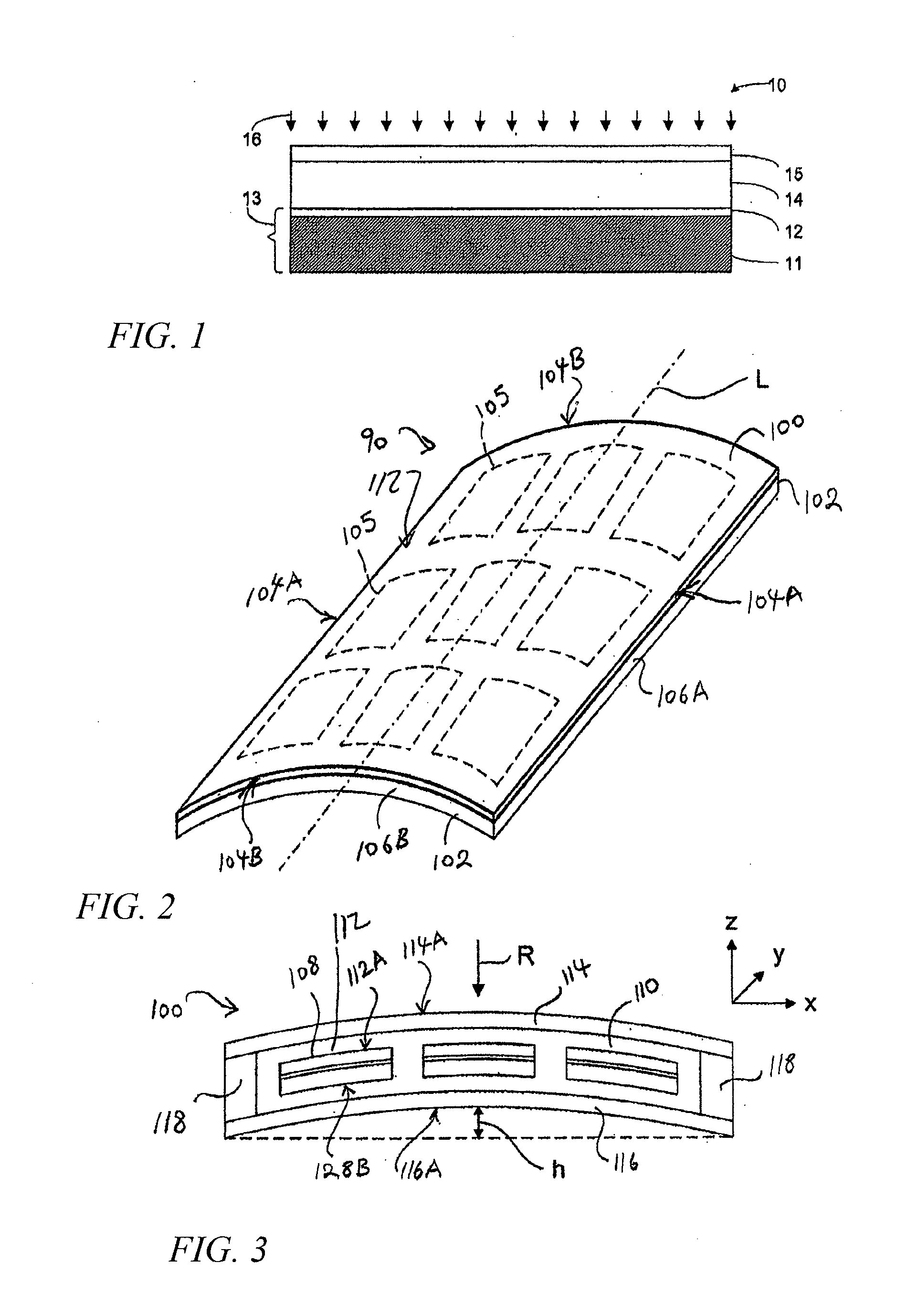
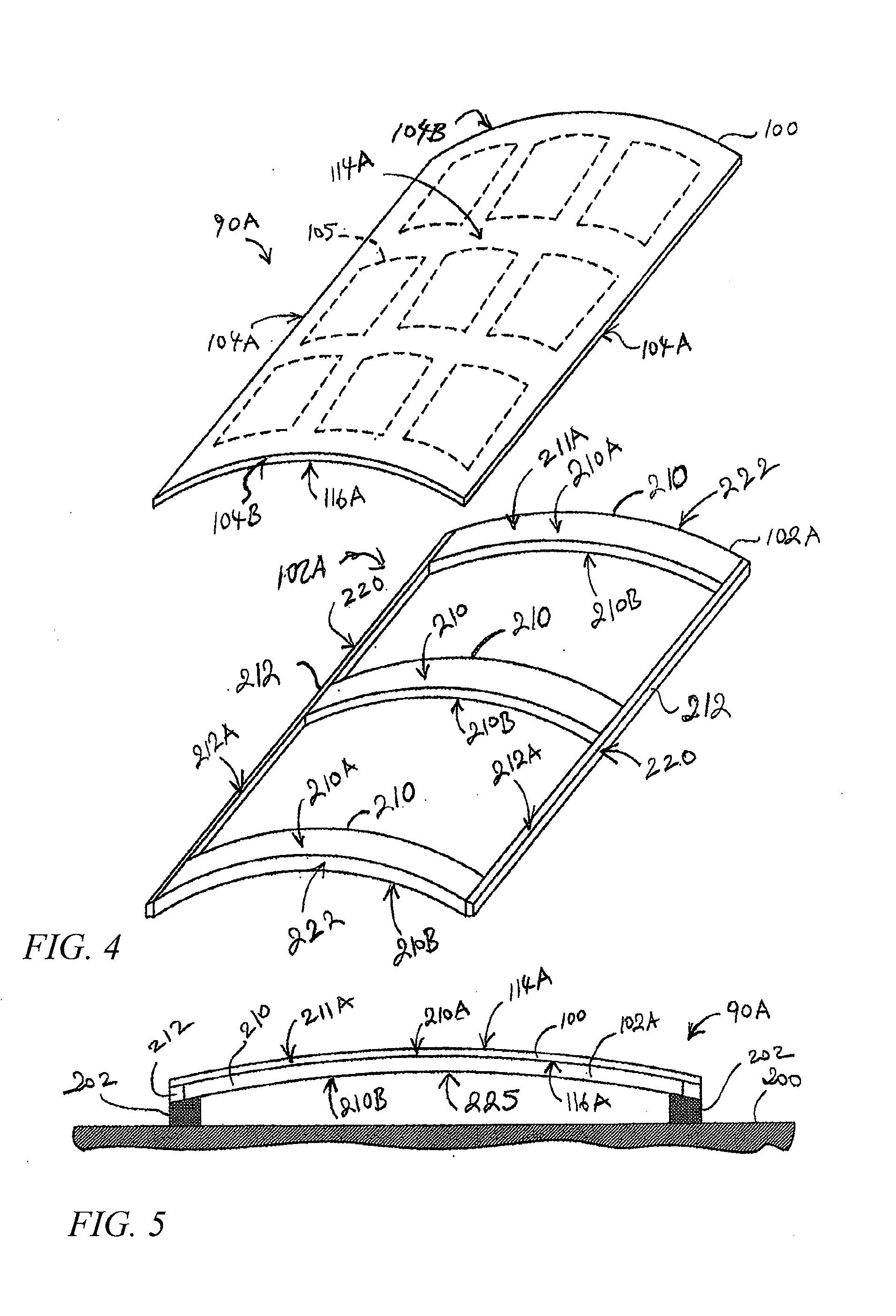
[0046]The preferred embodiments described herein provide a solar module including a curved or angled module body or shell defined by a convexly curved or angled top transparent layer and a bottom layer which may be curved or angled and which may conform to the shape of the top transparent layer. The curved or angled transparent top layer is placed over the bottom layer, and a plurality of solar cells is disposed between the top transparent layer and the bottom layer. The plurality of solar cells includes a light receiving side facing the top transparent layer. Curvature or angling of the module provides structural strength to the module without increasing its weight, thereby allowing maximum snow load and facilitating shedding of water, snow or other precipitation. In another embodiment of the present invention a solar module assembly including the convexly curved or angled module and a curved or angled support frame or chassis to retain the solar module is provided. In one embodime...


PUM


Abstract

A solar module having a curved surface to facilitate shedding of accumulated snow and water. The module can also be angled to achieve the same. The module includes a housing with a curved or angled upper surface and solar cells are positioned within the housing.

Description

RELATED APPLICATIONS[0001]This application is a Continuation in Part of U.S. application Ser. No. 13 / 333,966 filed Dec. 21, 2011 entitled INTEGRATED STRUCTURAL SOLAR MODULE AND CHASSIS.BACKGROUND[0002]1. Field of the Inventions[0003]The present inventions generally relate to solar panels and, more particularly, to design and manufacturing of solar panels including flexible thin film solar cells and solar panel assemblies including such solar panels.[0004]2. Description of the Related Art[0005]Solar cells are photovoltaic (PV) devices that convert sunlight directly into electrical energy. Solar cells can be based on crystalline silicon or thin films of various semiconductor materials that are usually deposited on low-cost substrates, such as glass, plastic, or stainless steel.[0006]Thin film based photovoltaic cells, such as amorphous silicon, cadmium telluride, copper indium diselenide or copper indium gallium diselenide based solar cells offer improved cost advantages by employing ...

Claims


Application Information

Patent Timeline
IPC IPC(8): H01L31/048E04B7/00E04D13/18
CPCY02E10/50Y02B10/12H01L31/048H02S20/00Y02E10/47H02S20/23F24J2/5235F24J2/5245Y02B10/20H02S30/10F24S25/15F24S25/61H02S20/30Y02B10/10
Inventor KHOURI, BRUCEENSOR, MARK
Owner SOLOPOWER
Why Eureka
Try Eureka