Display supporting device

a technology for supporting devices and displays, applied in the direction of machine supports, building scaffolds, other domestic objects, etc., can solve the problems of high production cost, complicated assembly process, and restricted lateral angle adjustment, and achieve the effect of improving wire management and enhancing aesthetics

Inactive Publication Date: 2013-06-27
FLYTECH TECH
View PDF3 Cites 12 Cited by
  • Summary
  • Abstract
  • Description
  • Claims
  • Application Information

AI Technical Summary

Benefits of technology

[0008]The object of the present invention is to provide a display supporting device having both vertical and horizontal angle adjusting mechanisms with wire concealing capability for providing improved wire management and enhanced aesthetics. The display supporting device includes a vertically adjustable pivotable head rotatably coupled to an end of a hollow supporting sleeve to enable horizontal angle adjustment. The exposed wires / cables of the supported display unit may pass through the hollow supporting sleeve, therefor hidden away from external sight.

Problems solved by technology

Conventional computer monitor supporting devices only allow pivotable adjustment in the vertical plane, resulting in the restricted lateral angle adjustment.
Though some improved display supporting devices allow pivotable adjustment in multiple directions, the structural design of such supporting devices tends to be too complicated, resulting in complicated assembly process and high production cost.
It is often difficult to neatly bundle and properly manage the cables to maintain a clean and orderly appearance.

Method used


Image

  • Display supporting device
  • Display supporting device
  • Display supporting device

Examples


Embodiment Construction

[0019]The aforementioned illustrations and following detailed descriptions are exemplary for the purpose of further explaining the scope of the present invention. Other objectives and advantages related to the present invention will be illustrated in the subsequent descriptions and appended drawings.

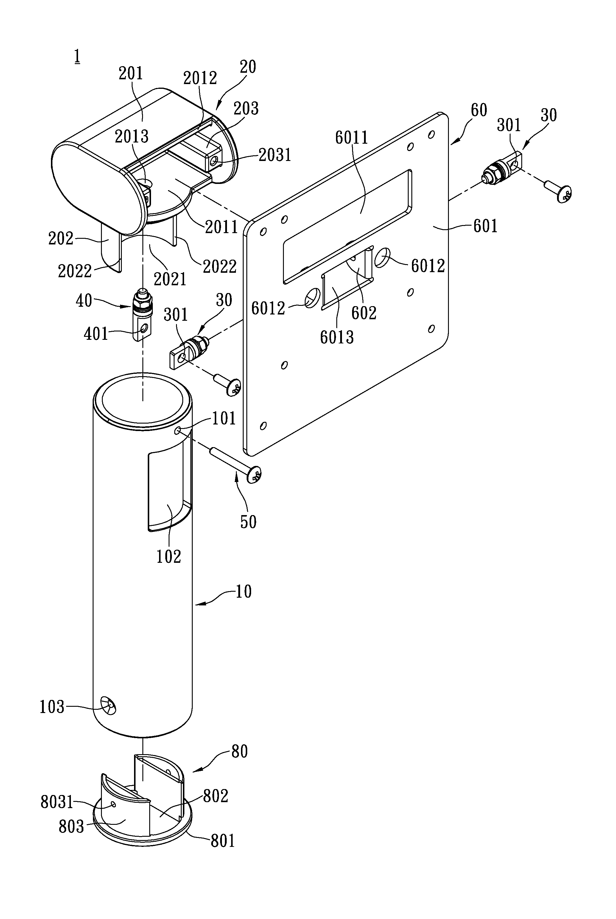
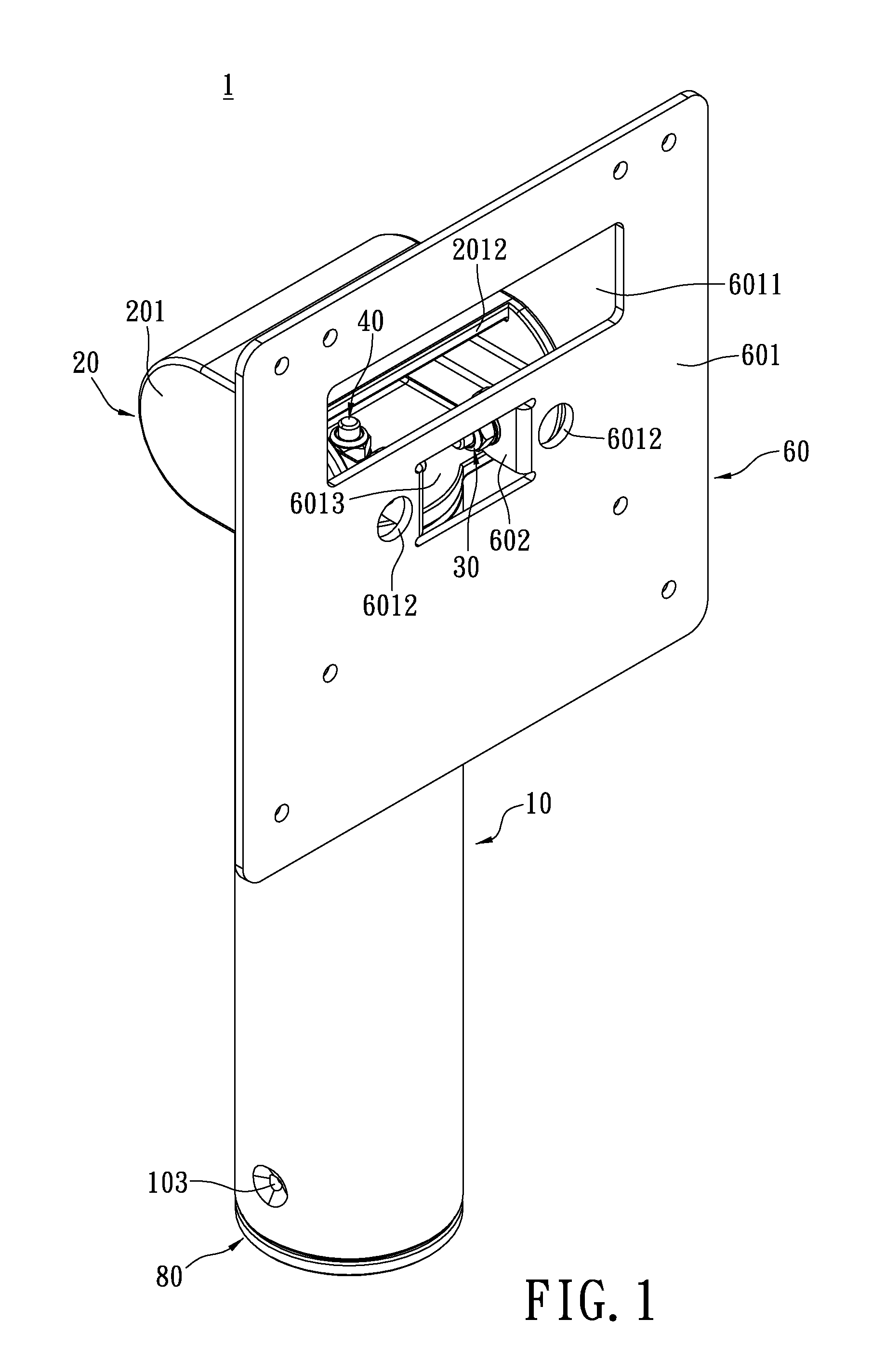
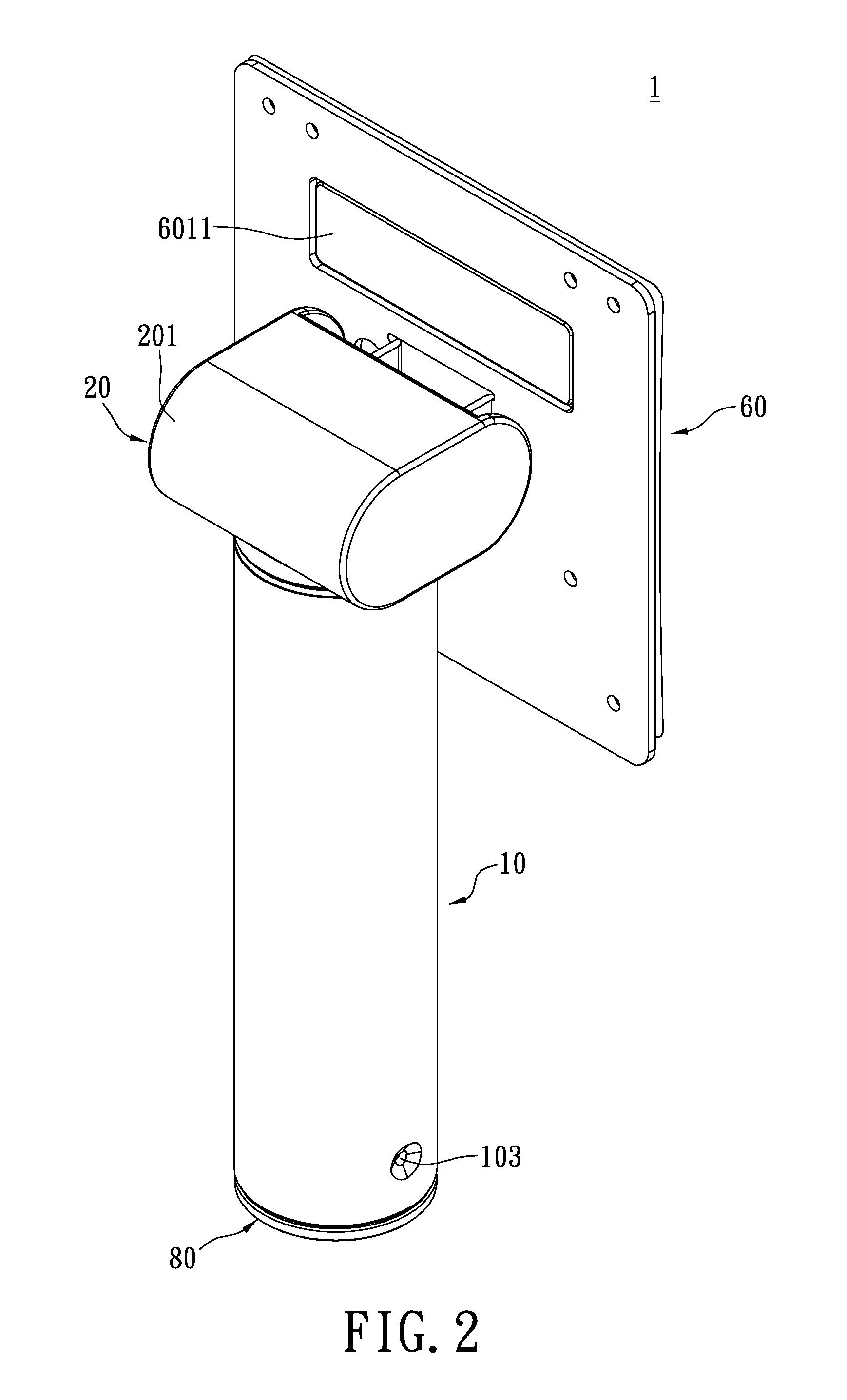
[0020]Referring now to FIGS. 1-4, the embodiment of the present invention provides a display supporting device to support the display unit D (shown in FIG. 7), the display unit D is connected to a plurality of exposed wires (not shown), the supporting device 1 comprises: a supporting sleeve 10, a pivotable head 20, two first fasteners 30, a second fastener 40 and a third fastener 50 wherein the display unit D is fastened adjacently to the first fastener 30.

[0021]Referring now to FIG. 3&FIG. 4, the supporting sleeve 10 has a circular hollow transverse cross-section, a penetrating hole 101 on the side wall thereof, and an opening 102, and the penetrating hole 101 is located between the piv...


PUM


Abstract

A display supporting device comprises a supporting sleeve, a pivotable head, a first fastener, a second fastener, and a third fastener. The supporting sleeve has a circular hollow cross-section and a penetrating hole on the side wall thereof The pivotable head has a head portion and a neck portion. The neck portion has two stopping sections and is adapted to rotatably couple the supporting sleeve to enable lateral angle adjustment. The first fastener is arranged in the pivotable head for coupling a display unit. The second fastener has an attaching hole correspondingly aligns the penetrating hole, enabling horizontal rotation of the pivotable head about the second fastener. The third fastener passes through the penetrating hole of the supporting sleeve and the attaching hole of the second fastener. The horizontal rotation of the pivotable head is restricted through the contact between the stopping sections thereof and the third fastener.

Description

BACKGROUND OF THE INVENTION[0001]1. Field of the Invention[0002]The present invention relates to a display supporting device, and more particularly, to a display supporting device having wire concealing capability for providing improved wire management and enhanced aesthetics.[0003]2. Description of Related Art[0004]Conventional computer monitor supporting devices only allow pivotable adjustment in the vertical plane, resulting in the restricted lateral angle adjustment.[0005]Though some improved display supporting devices allow pivotable adjustment in multiple directions, the structural design of such supporting devices tends to be too complicated, resulting in complicated assembly process and high production cost.[0006]Furthermore, conventional monitor displays require at least one exposed wire / cable for establishing signal connection with the host machine. It is often difficult to neatly bundle and properly manage the cables to maintain a clean and orderly appearance.[0007]To add...

Claims


Application Information

Patent Timeline
Patent Type & Authority Applications(United States)
IPC IPC(8): H05K7/00
CPCF16M11/10F16M2200/08F16M2200/065F16M11/2014
Inventor LIN, CHIUNG-CHICHEN, YA-QIU
Owner FLYTECH TECH
Why Eureka
Try Eureka