Magnetic fluid seal

Active Publication Date: 2013-06-27
EAGLE INDS
View PDF30 Cites 6 Cited by
  • Summary
  • Abstract
  • Description
  • Claims
  • Application Information

AI Technical Summary

Benefits of technology

[0021]As described above, the present invention is capable of producing the stable sealing performan

Problems solved by technology

Meanwhile, in the case of a magnetic fluid seal, there is a disadvantage in that a structure for stably holding a magnetic fluid in place between two members rotating relative to each other is difficult in comparison wi

Method used


Image

  • Magnetic fluid seal
  • Magnetic fluid seal
  • Magnetic fluid seal

Examples


Example

Example 1

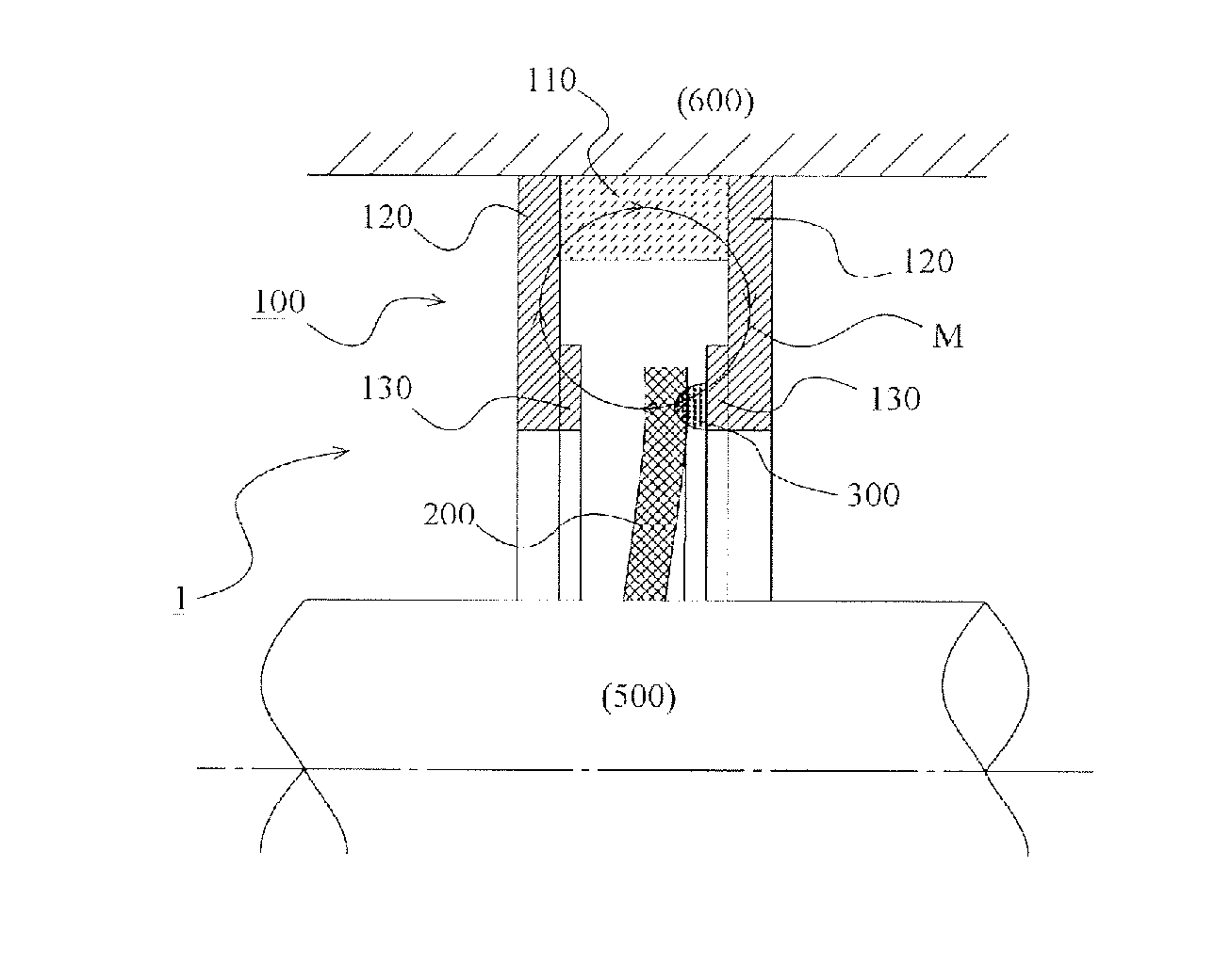
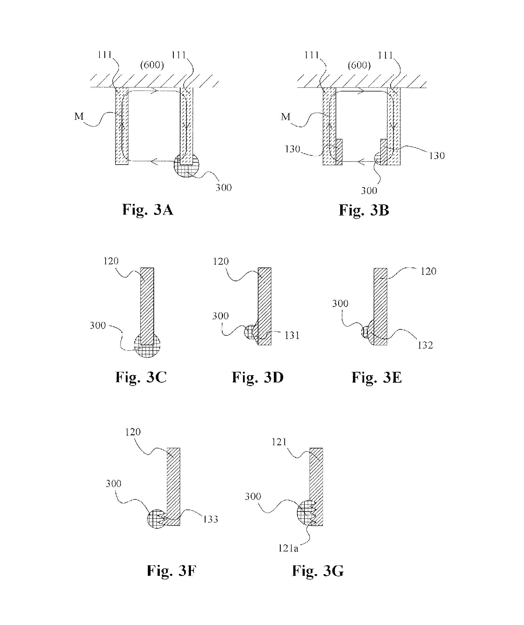
[0036]A description will be given of a magnetic fluid seal according to Example 1 of the present invention, with reference to FIGS. 1 to 3G. Note that a magnetic fluid seal 1 according to this Example is applicable to agitators, gas seals for VOC measures, various industrial apparatus such as vacuum devices for manufacturing semiconductors, fishing reels, shaft parts for various devices such as bicycles, as a leak prevention seal or a dust seal.

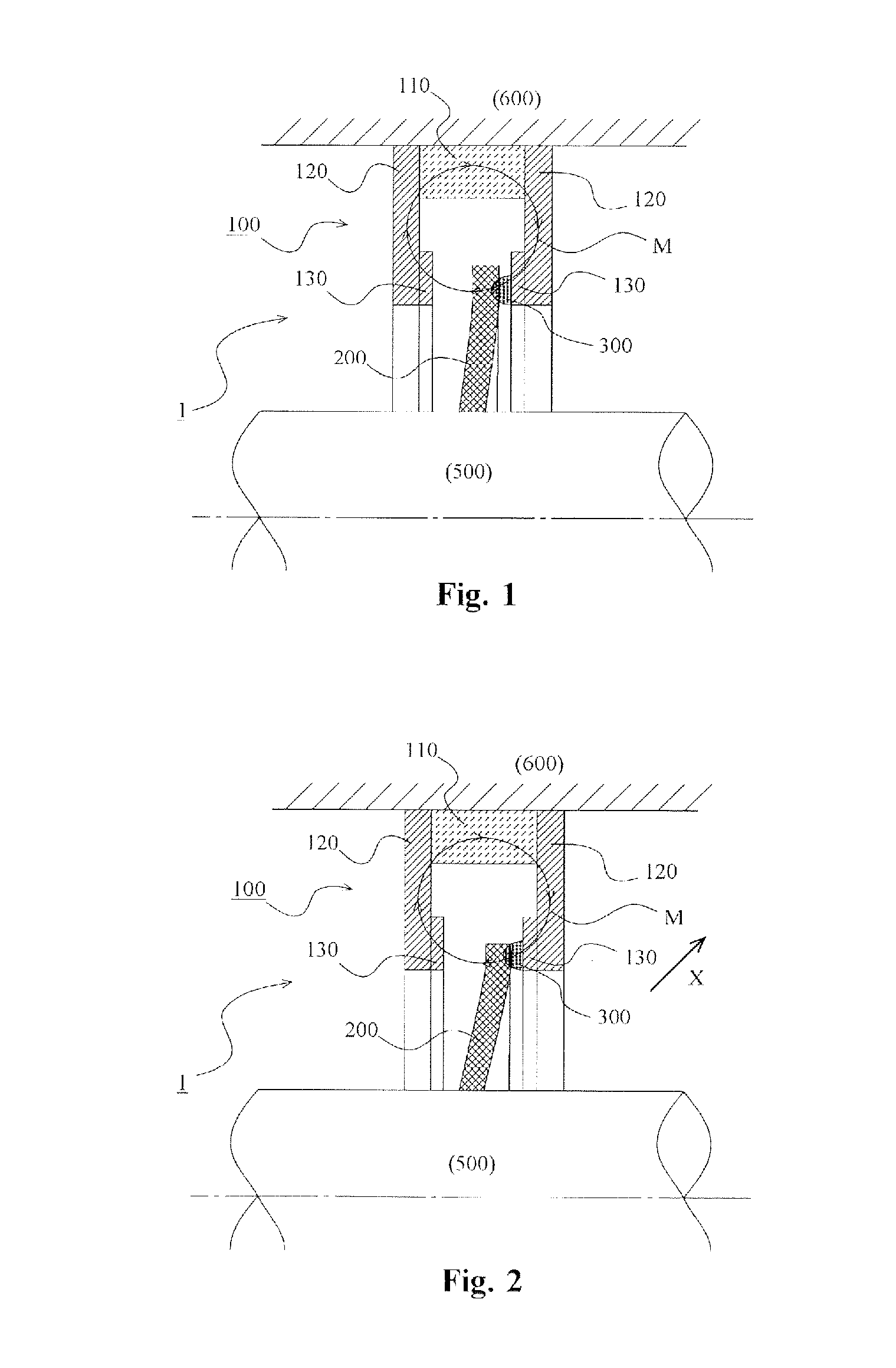
[0037]A description will be given of an overall configuration of a magnetic fluid seal according to Example 1 of the present invention, in particular, with reference to FIG. 1. FIG. 1 shows a stationary state (when a shaft 500 and a housing 600, or two members, are stationary).

[0038]The magnetic fluid seal 1 is provided to seal an annular gap between the shaft 500 and the housing 600 that rotate relative to each other (including not only a case where one rotates and the other is stationary, but also a case where both rotate). In addi...

Example

Example 2

[0062]FIGS. 4A to 4D illustrate Example 2 according to the present invention. This Example will describe a configuration where an annular dispersion preventing member is provided to prevent a magnetic fluid from being dispersed, in addition to the above configuration exemplified in Example 1. The same reference numerals are assigned to the same components as those of Example 1, and descriptions therefor will be omitted as appropriate. Note that FIGS. 4A to 4D illustrate schematic cross-sectional views of a magnetic fluid seal, and only a cut surface obtained by cutting the main part is illustrated.

[0063]This Example exemplifies a case where an annular dispersion preventing member that prevents a magnetic fluid 300 from being dispersed is disposed radially outward of a portion on which the magnetic fluid 300 is magnetically held.

[0064]In an example illustrated in FIG. 4A, an annular dispersion preventing member 410 is disposed on the magnetic pole member 120. This dispersion...

Example

Example 3

[0070]FIG. 5 illustrates Example 3 of the present invention. Example 1 described above has exemplified the configuration where the single annular member holds the magnetic fluid at a single location, whereas this Example has exemplified a configuration where two annular members hold a magnetic fluid at two locations. The same reference numerals are assigned to the same components as those of Example 1, and descriptions therefor will be omitted as appropriate. FIG. 5 illustrates a schematic cross-sectional view of a magnetic fluid seal, and only a cut surface obtained by cutting the main part.

[0071]As illustrated in FIG. 5, a configuration of a magnetic circuit forming member 100 is the same as that of Example 1. In this Example, two annular members 200 are disposed on a shaft 500. The configuration itself of each annular member 200 is the same as that of Example 1 described above.

[0072]Respective configurations of magnetically holding a magnetic fluid 300 are employed betwe...


PUM


Abstract

A magnetic fluid seal is provided, that is capable of producing a stable sealing performance by stably holding the magnetic fluid in place, even in cases when the two members become eccentric. The magnetic fluid seal includes: an annular magnetic circuit forming member 100 that is disposed on a housing 600; an annular member 200 that is disposed on a shaft 500; and a magnetic fluid 300 that is magnetically held between axially opposing surfaces of the magnetic circuit forming member 100 and the annular member 200. In addition, the annular member 200 comprises a flexible member that is swayable so that a portion of the annular member 200 that opposes the magnetic circuit forming member 100 follows the magnetic circuit forming member 100.

Description

TECHNICAL FIELD[0001]The present invention relates to a magnetic fluid seal to seal an annular gap between two members rotating relative to each other.BACKGROUND ART[0002]In the past, magnetic fluid seals have been known, which seal an annular gap between two members that rotate relative to each other. As for a magnetic fluid seal, there is an advantage in that friction torque can be extremely decreased, in comparison with a seal composed of a rubber, a resin, or the like. Meanwhile, in the case of a magnetic fluid seal, there is a disadvantage in that a structure for stably holding a magnetic fluid in place between two members rotating relative to each other is difficult in comparison with a solid material such as a rubber, a resin, or the like.[0003]In order to stably hold a magnetic fluid in place, there is a need to stably form a magnetic circuit and to decrease the variation in a region (space) where a magnetic fluid is held. Accordingly, in cases when the two relatively rotati...

Claims


Application Information

Patent Timeline
IPC IPC(8): F16J15/43
CPCF16J15/43F16J15/447
Inventor FUKUHARA, TAKUTO
Owner EAGLE INDS
Why Eureka
Try Eureka