Holding apparatus, holding method, exposure apparatus and device manufacturing method

a technology of holding apparatus and holding method, which is applied in the direction of photomechanical apparatus, printing, instruments, etc., can solve the problems of reticle r distortion, affecting so as to improve the overall surface precision of the mask, increase the size of the whole surface of the mask, and ensure the effect of mask retention

Inactive Publication Date: 2006-07-06
NIKON CORP
View PDF8 Cites 3 Cited by
  • Summary
  • Abstract
  • Description
  • Claims
  • Application Information

AI Technical Summary

Benefits of technology

[0027] According to the method and apparatus described above, the first attraction holding sections can hold the mask stably, without deteriorating the ov...

Problems solved by technology

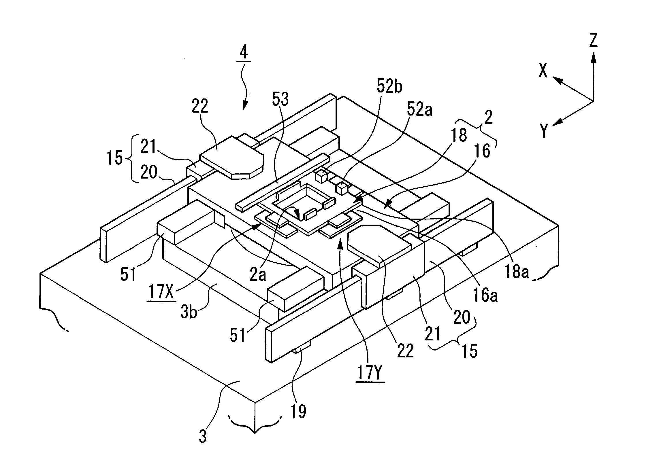
In this case, the contact surface of the reticle R with respect to the suction pads 106 is distorted, and this distortion affects even the area having predetermined surface precision (hereinafter referred to as a “precision warrantable area”) to decrease the surface precision, thereby causing a problem in that high precision...

Method used


Image

  • Holding apparatus, holding method, exposure apparatus and device manufacturing method
  • Holding apparatus, holding method, exposure apparatus and device manufacturing method
  • Holding apparatus, holding method, exposure apparatus and device manufacturing method

Examples


second embodiment

[0133]FIG. 15 to FIG. 21 illustrate a second embodiment of the present invention. This embodiment has a feature in that a so-called pin and chuck holder is used as a reticle holder 90. Other configuration of the apparatus is the same as that of the first embodiment described above.

[0134]FIG. 15 is a perspective view of the reticle holder 90. A rectangular opening 2a is formed at the center of the reticle holder 90, and suction pads 91 having a long and slender rectangular shape are formed on the opposite sides of the opening 2a on the upper face of the reticle holder 90, each aligned along the side of the opening 2a.

[0135] These suction pads 91 have, respectively, a partition wall 92 which surrounds a rectangular decompression area 95 for maintaining the degree of vacuum, a plurality of pins 96 formed in the decompression area 95, with intervals therebetween, and exhaust holes 94 which open into the decompression area 95. The width and height of the partition wall 92 are constant ...

third embodiment

[0143] In the present invention, by placing a reticle R with the end of the reticle R being curved, as shown in FIG. 23 and FIG. 24, instead of forming the tapered portion at the end of the reticle R, a similar effect can be obtained. This point will be described below.

[0144] As shown in FIG. 22, when a stress P is applied perpendicularly to the upper face of the reticle, at the opposite ends of a flat reticle R having a uniform thickness, at a position of distance x from one end of the reticle R, a stress, a shearing force, a bending moment and flexure expressed by the following equations occur, where l1 denotes an interval between a central supporting point and an outside supporting point of the reticle R in the attraction holding section (first attraction holding section) of the reticle holder, l2 denotes an interval between the central supporting points in the respective attraction holding sections, δ denotes an interval (gap) between the outside supporting point and the reticl...


PUM


Abstract

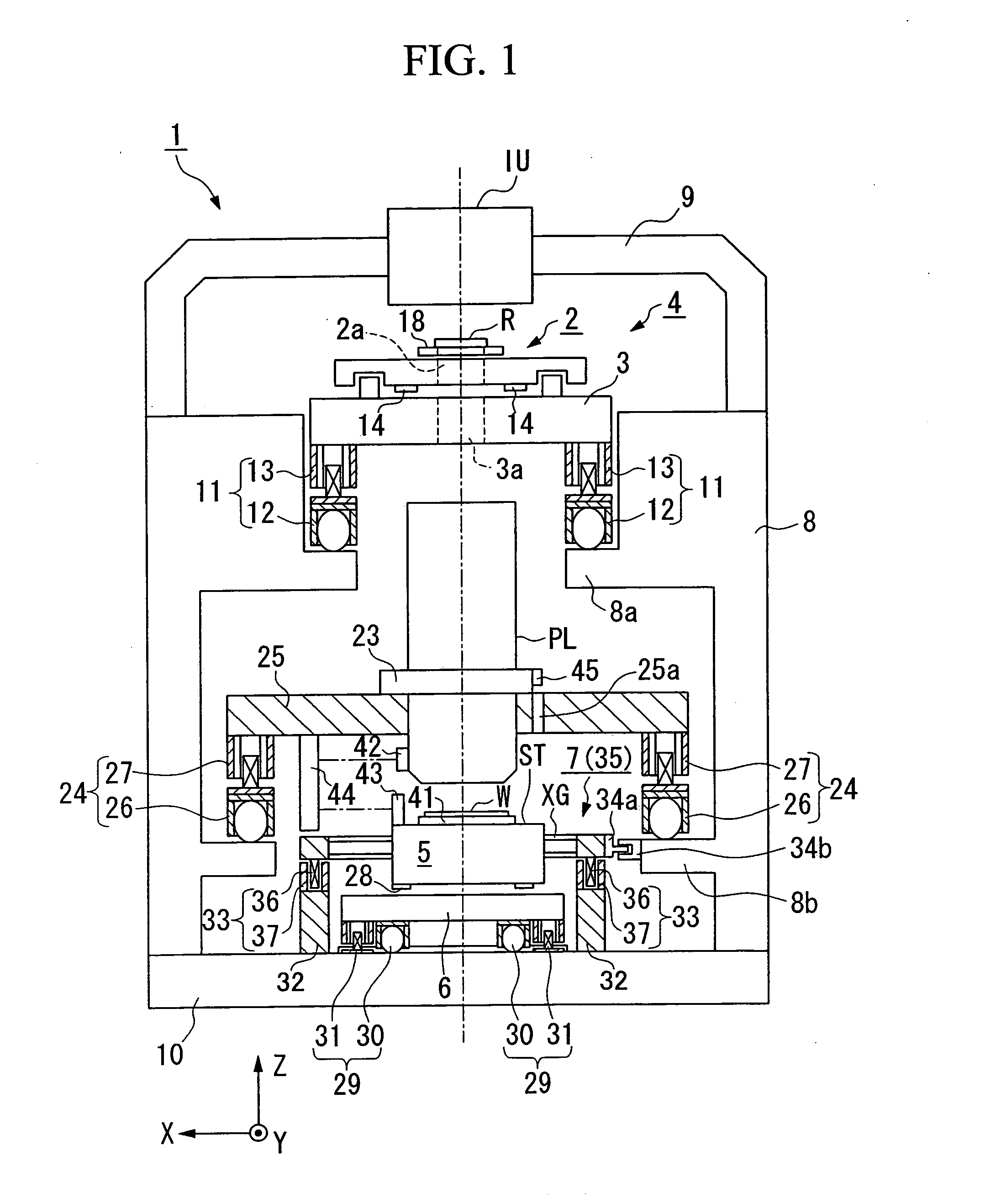
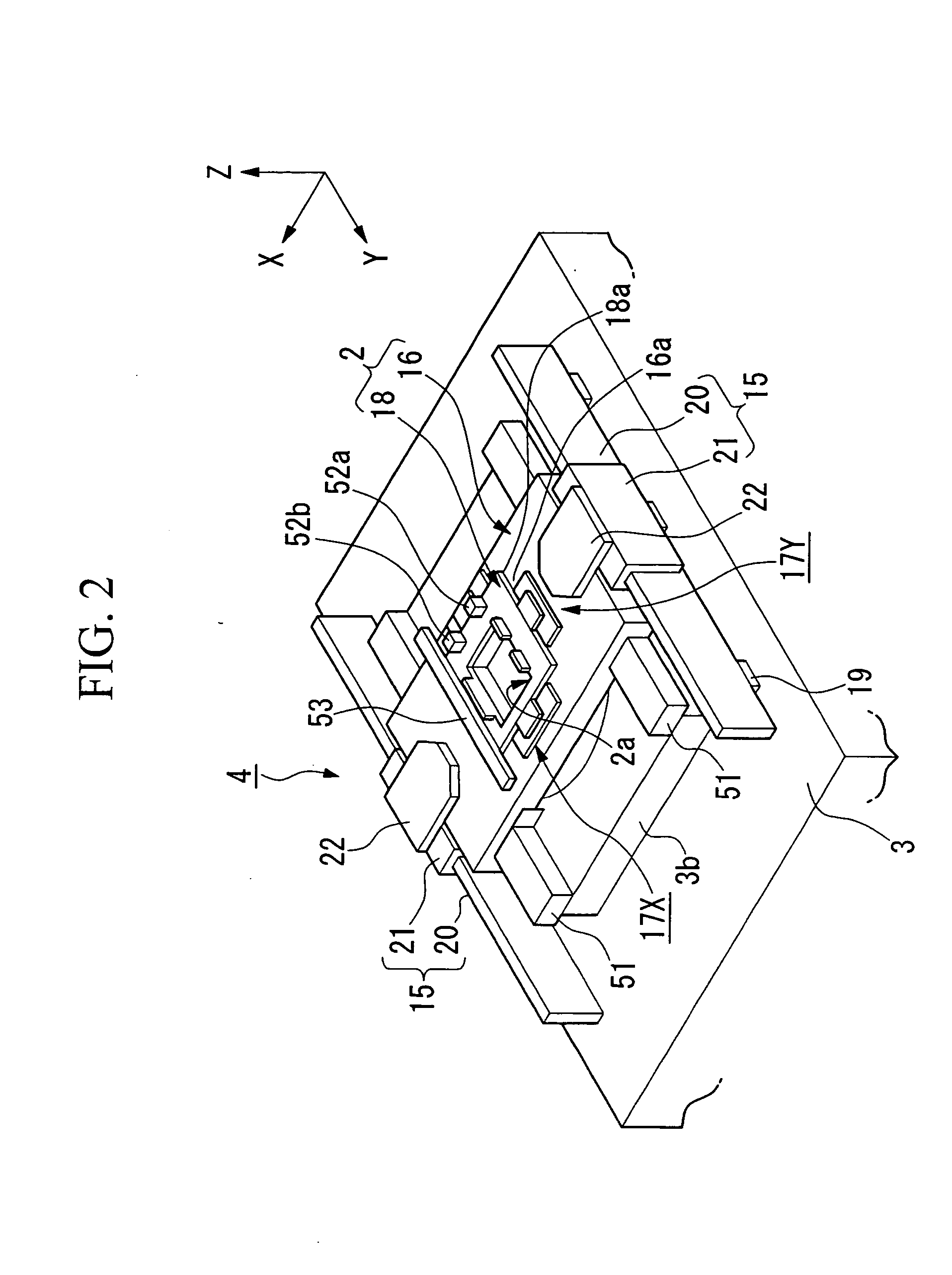
A reticle holder has a first suction section facing a precision warrantable area having a predetermined surface precision, of a lower face of a reticle, a second suction section facing a precision unwarrantable area outside of the precision warrantable area, a pore connected to a suction apparatus that draws out gas in a space between the lower face of the reticle and the first suction section, and a pore connected to the suction apparatus and that draws out gas in the space between the lower face of the reticle and the second suction section. As a result, the reticle can be held stably, without deteriorating the surface precision of the precision warrantable area.

Description

[0001] This is a Continuation of U.S. patent application Ser. No. 10 / 639,651 filed Aug. 13, 2003, which in turn is a Continuation of International Application No. PCT / JP02 / 01200 filed Feb. 13, 2002. Furthermore, priority is claimed under 35 U.S.C. §119 to Japanese Patent Application No. 2001-036130 filed Feb. 13, 2001. The disclosures of all of these prior applications are incorporated herein by reference in their entireties.BACKGROUND OF THE INVENTION [0002] 1. Field of the Invention [0003] The present invention relates to a holding apparatus and a holding method, and an exposure apparatus which uses a mask and a substrate held by the holding apparatus to expose a mask pattern onto the substrate. More specifically, the present invention relates to a holding apparatus and a holding method, an exposure apparatus and a device manufacturing method, suitable for use in a lithography process, particularly when devices such as liquid crystal display elements and semiconductor elements are...

Claims


Application Information

Patent Timeline
IPC IPC(8): G03B27/58G03F7/20H01L21/683
CPCG03F7/707G03F7/70833H01L21/6838H01L21/027
Inventor HAGIWARA, TSUNEYUKIYOSHIMOTO, HIROMITSUHORIKAWA, HIROTOMIZUTANI, HIDEO
Owner NIKON CORP
Why Eureka
Try Eureka