
Method for producing pneumatic tire

Inactive Publication Date: 2013-01-03
YOKOHAMA RUBBER CO LTD
View PDF0 Cites 2 Cited by
  • Summary
  • Abstract
  • Description
  • Claims
  • Application Information

AI Technical Summary

Benefits of technology

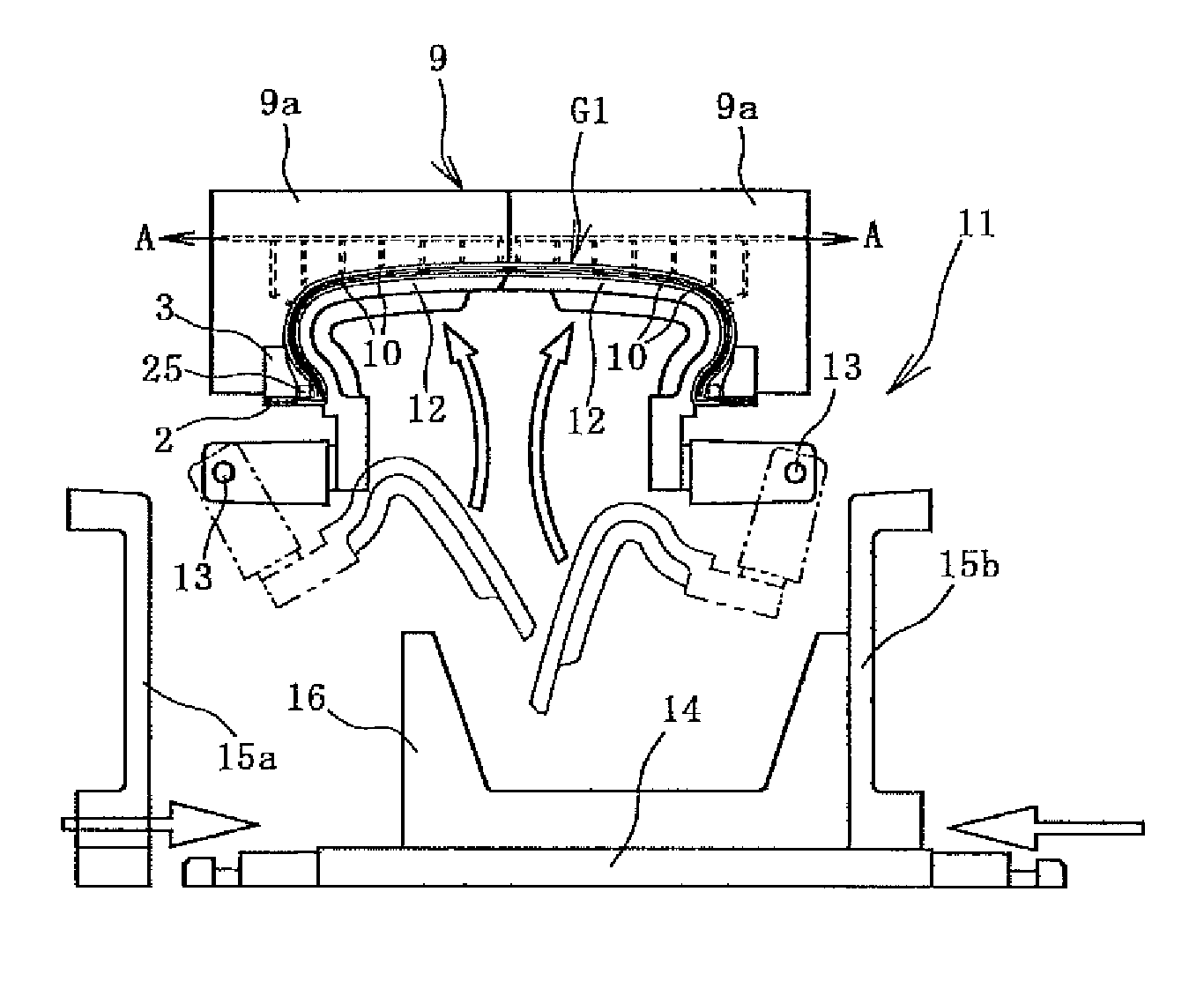
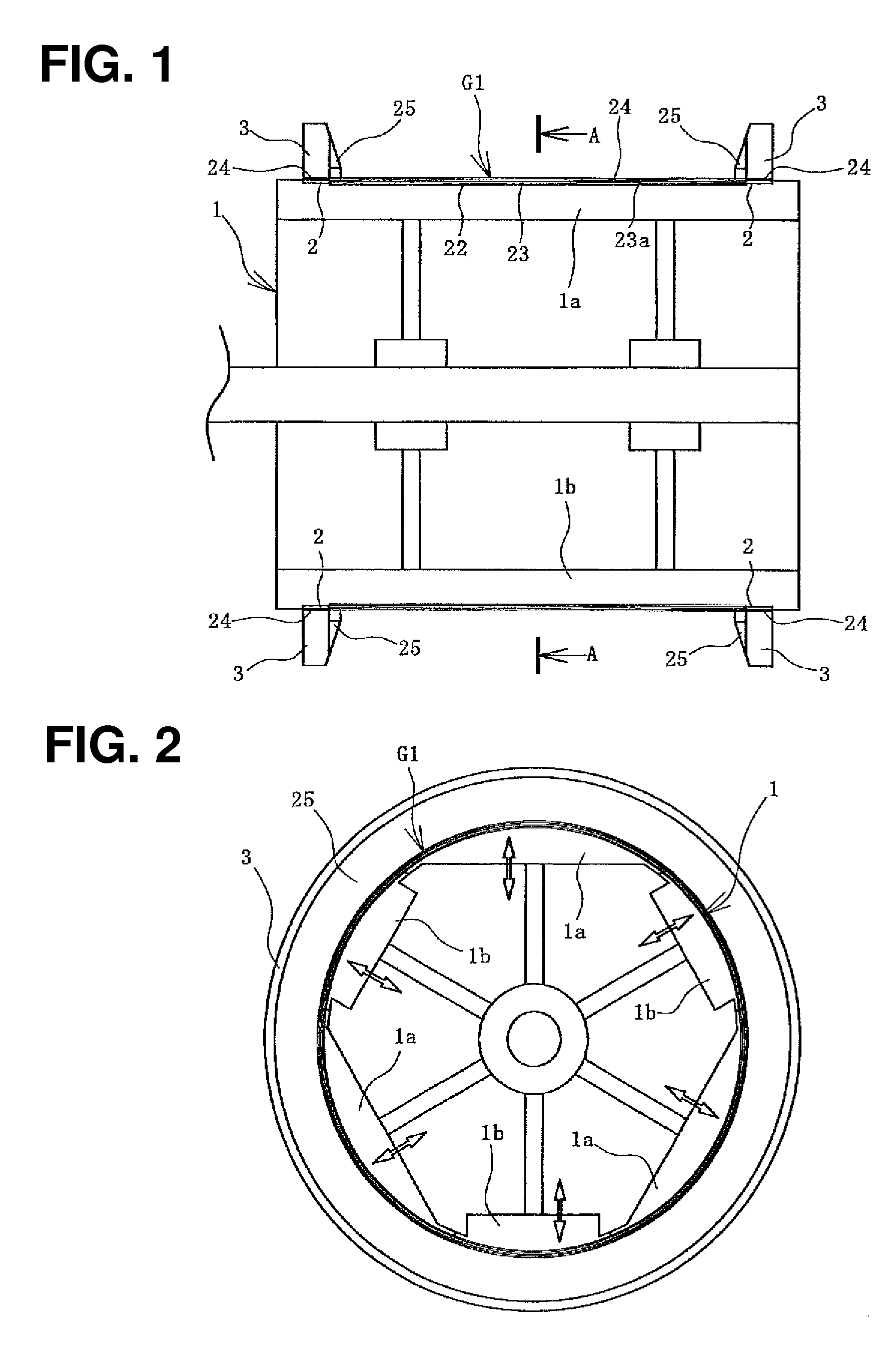
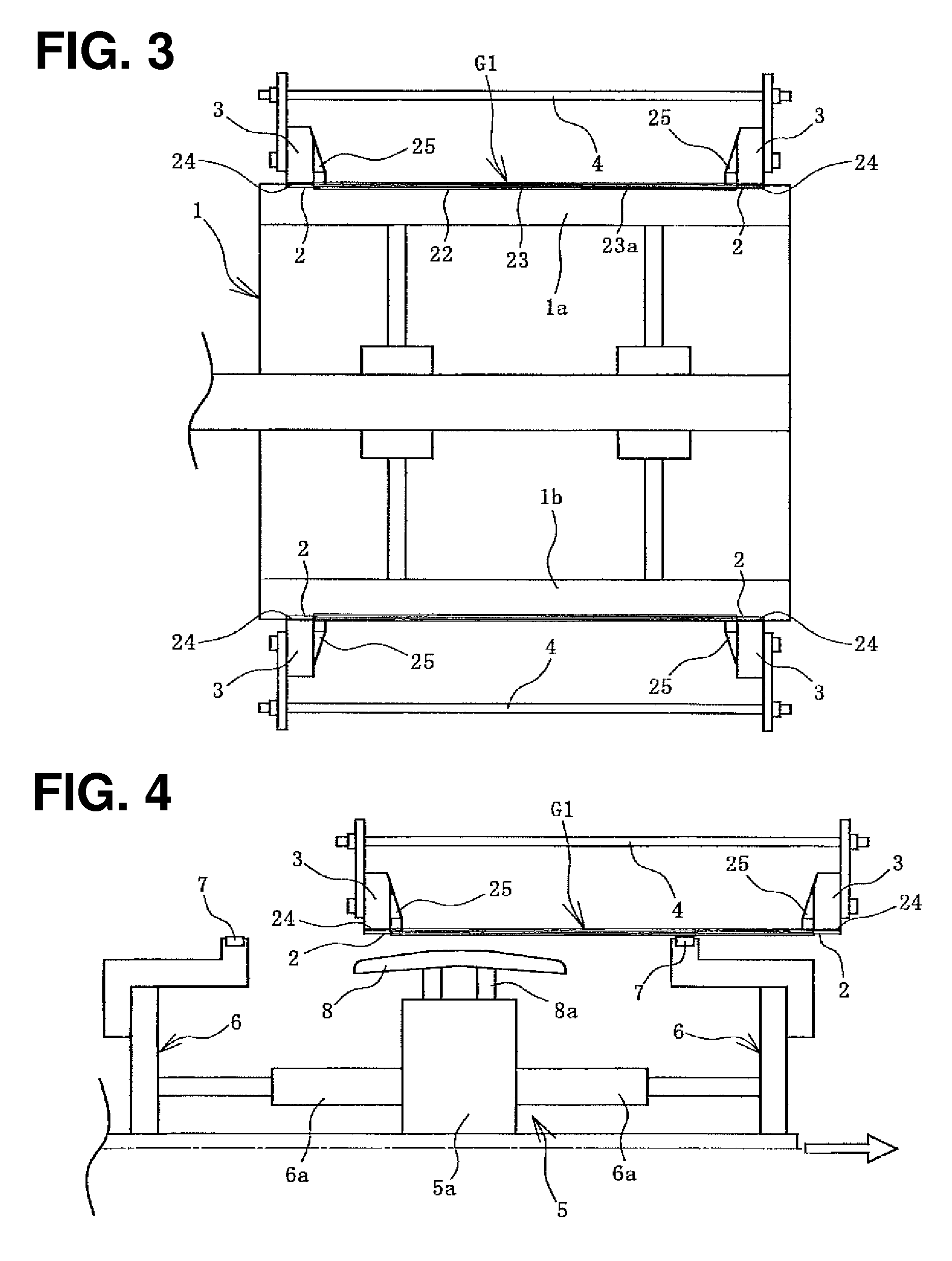
The present invention relates to a method for producing a pneumatic tire. The method involves layering a film made of thermoplastic resin or thermoplastic elastomer composition on the inner peripheral surface of a primary formed body, which is then held by suction on a rigid inner mold and transferred to a vulcanizing mold. This allows for a green tire to be formed that is precisely fitted to the rigid inner mold, improving the uniformity of the tire to be produced. The green tire is then vulcanized and the inner liner is inflated with heating fluid, correcting any unevenness in the tire-constituting members. The use of the thermoplastic resin or thermoplastic elastomer composition makes the tire lighter and provides better air-permeation prevention performance than conventional inner liners made of butyl rubber alone. The formed green tire is supported by the rigid inner mold until vulcanized, reducing unnecessary deformation. The rigid inner mold can be used repeatedly, improving productivity. The transferring / holding mold can be positioned on the outer peripheral side of the primary formed body, making it easier to fit the primary formed body to the inner peripheral surface of the transferring / holding mold.

Problems solved by technology

However, it is difficult to form a green tire by stably layering tire-constituting members such as an inner liner, while fitting these tire-constituting members to an outer peripheral surface of the rigid inner mold.
This difficulty is a factor of hindering the improvement in uniformity of a tire.
Hence, the inner liner is disadvantageous for the weight reduction of a tire.

Method used


Image

  • Method for producing pneumatic tire
  • Method for producing pneumatic tire
  • Method for producing pneumatic tire

Examples


Embodiment Construction

[0057]Hereinafter, methods for producing a pneumatic tire of the present invention are described based on embodiments shown in the drawings. Note that the same members are denoted by the same reference signs before and after vulcanization.

[0058]FIG. 18 illustrates a pneumatic tire 21 produced by the present invention. In the pneumatic tire 21, a carcass material 24 is laid between a pair of bead rings 25, and is folded back around bead cores 25a from the inside to the outside, with bead fillers 25b sandwiched therebetween. A tie rubber 23a, a film 23, and an inner liner 22 are layered in this order on an inner peripheral side of the carcass material 24. The inner liner 22 at the innermost periphery is a vulcanized butyl rubber, and prevents air permeation together with the film 23. The thickness of the inner liner 22 is, for example, 0.2 mm to 2.5 mm. The thickness of the film 23 is, for example, 0.005 mm to 0.2 mm.

[0059]The film 23 and the carcass material 24 are joined to each oth...


PUM

PropertyMeasurementUnit
Pressureaaaaaaaaaa
Pressureaaaaaaaaaa
Temperatureaaaaaaaaaa

Abstract

A primary formed body is formed by fitting bead rings to outside end portions of a cylindrical body having an inner liner, a film layered on an outer peripheral side of the inner liner, and a carcass material disposed on an outer peripheral side of the film. A green tire is formed on an outer peripheral surface of a rigid inner mold by prevulcanizing the inner liner in a state where a center portion of the primary formed body bulges toward an outer peripheral side, and is held by suction on an inner peripheral surface of a transferring / holding mold to the outer peripheral surface of the rigid inner mold, placing the rigid inner mold inside the primary formed body, then suspending the suction with the transferring / holding mold, and transferring the primary formed body to the outer peripheral surface of the rigid inner mold. The green tire is vulcanized.

Description

TECHNICAL FIELD[0001]The present invention relates to a method for producing a pneumatic tire, and more specifically to a method for producing a pneumatic tire, the method being capable of producing a light-weight pneumatic tire excellent in air-permeation prevention performance and uniformity.BACKGROUND ART[0002]Various methods for producing a pneumatic tire have been proposed in which a green tire is formed on an outer peripheral surface of a rigid inner mold made of a metal, and the formed green tire is vulcanized, while being disposed inside a vulcanizing mold together with the rigid inner mold (for example, see Patent Document 1). Such a production method using a rigid inner mold enables the formation of a green tire having a similar shape to that of a tire to be produced, and hence makes it possible to reduce the load acting on the green tire during the vulcanization.[0003]However, it is difficult to form a green tire by stably layering tire-constituting members such as an inn...

Claims


Application Information

Patent Timeline
IPC IPC(8): B29D30/08
CPCB29D30/0681B29D2030/0655B29D2030/0682B29D2030/062B29D30/0661B29D30/10B29L2030/00B29C33/02B29C35/02B29D30/08
Inventor SANO, TAKUZOTAKADA, NOBORU
Owner YOKOHAMA RUBBER CO LTD
Learn More