Method and system for managing an electrical load of a user facility based on locally measured conditions of an electricity supply grid

Inactive Publication Date: 2013-06-27
COOPER TIMOTHY PATRICK
View PDF7 Cites 34 Cited by
  • Summary
  • Abstract
  • Description
  • Claims
  • Application Information

AI Technical Summary

Benefits of technology

[0021]The advantage of the present invention is that the measurement from the section of the grid which is adjacent the user terminal may be taken into account by the controller within the user terminal without extensive communication protocols and/or expensive communication hardware requirements. Moreover, due to the close geographical location of the controller to the locally-based measurement devices which provide the locally measured waveform conditions, the controller will be made aware of the waveform conditions in relative real-time as there will be very little time lag for the information to be sent from the locally-based measurements devices to the controller. This results in a more responsive system which can adapt to the variations and fluctuations on the electricity supply grid in a more instantaneous manner than any of the prior art systems and methods which continue to rely on a centralised controller approach.
[0022]The present invention is advantageous over PCT Patent Publication Number PCT/EP2004/010639 as PCT Patent Publication Number PCT/EP2004/010639 is clearly directed towards altering the load on an electrical network in order to suit the prevailing conditions on the electrical network. This is somewhat different to the concept of the present invention which is to locally control the importation or exportation of electrical energy to/from the grid depending on prevailing local conditions on the electricity sup

Problems solved by technology

In further scenarios, the operators of the grid connected on site generators may be able to export electricity to the electricity supply grid resulting in a financial gain.
The problem with current systems is that a large number of communication packets need to be sent between the centralised controller and the grid connected on site generator controller systems, which may advantageously form part of the aforementioned smart meters, in order for the centralised controller to instruct all of the grid connected on site generator controller systems to either import to or export from the electricity supply grid in a synchronised and organised fashion so as to have the desired effect on the electricity supply grid.
As one could imagine, the coordina

Method used


Image

  • Method and system for managing an electrical load of a user facility based on locally measured conditions of an electricity supply grid
  • Method and system for managing an electrical load of a user facility based on locally measured conditions of an electricity supply grid
  • Method and system for managing an electrical load of a user facility based on locally measured conditions of an electricity supply grid

Examples


Embodiment Construction

[0102]The invention will be more clearly understood from the following description of some embodiments thereof, given by way of example only with reference to the accompanying drawing, in which:

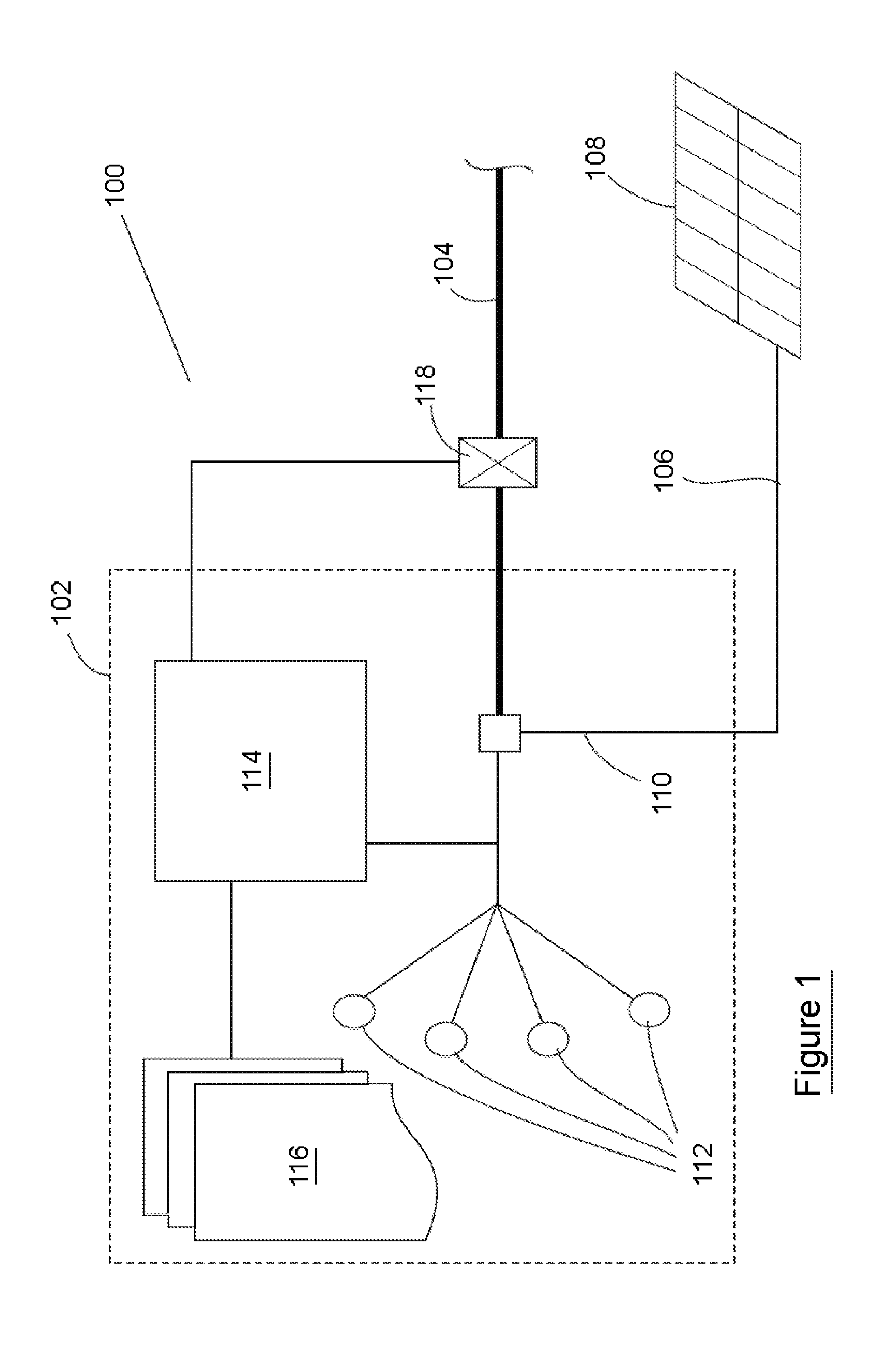
[0103]FIG. 1 is a diagrammatic representation of an electricity management system according to the present invention;

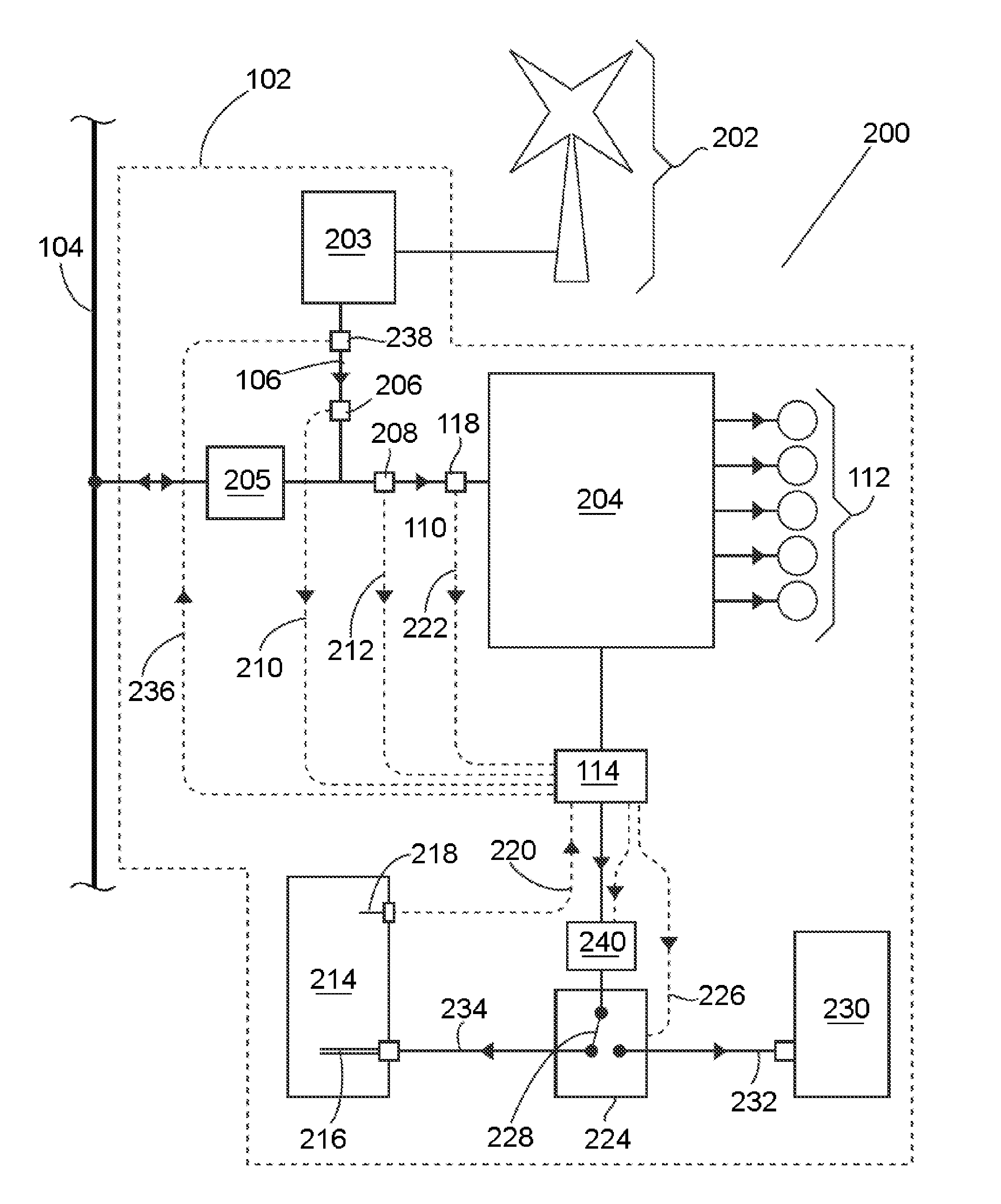
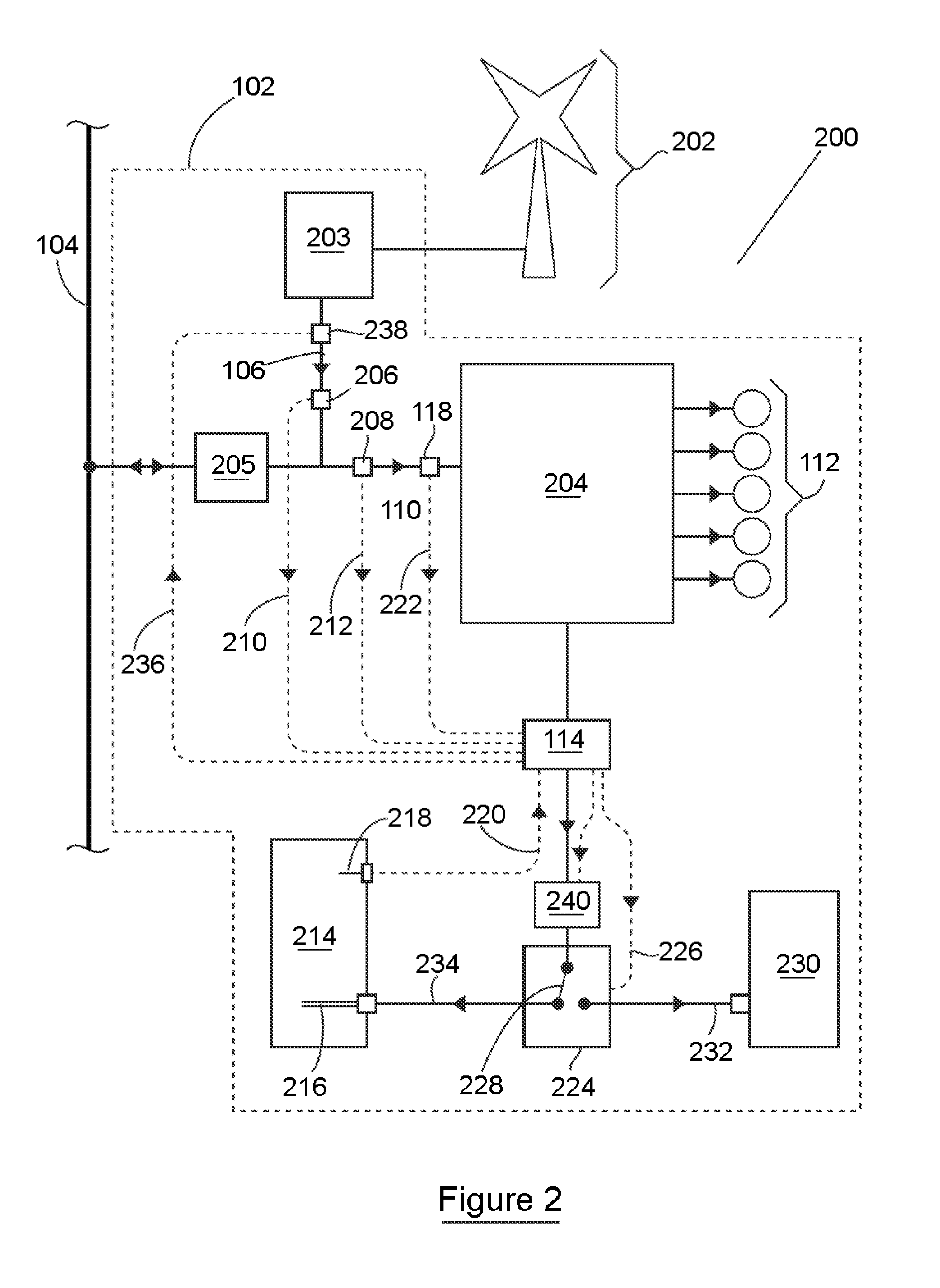
[0104]FIG. 2 is a diagrammatic representation of an electricity management system according to a further embodiment of the present invention;

[0105]FIG. 3 is a graph showing the controlled alteration of an overall load of a user terminal in response to the variation in the supply of electricity to the user terminal; and,

[0106]FIG. 4 is a graph showing a number of measurements within the user terminal during the operation of the present invention.

[0107]Referring to FIG. 1, there is provided an electricity management system indicated generally by the reference numeral 100. The electricity management system 100 is housed in a terminal user facility 102 such as a domestic residence,...


PUM


Abstract

The present invention relates to a method of managing the consumption and distribution of electricity in a user facility, wherein the user facility is connected to an electricity supply grid and the user facility comprises a grid connected on site generator; the method comprising the steps of measuring waveform conditions on a portion of the electricity supply grid adjacent the user facility to obtain locally measured waveform conditions; measuring electrical power readings from the on site generator; communicating the locally measured waveform conditions and the electrical power readings to a controller in the user facility; determining, at least on the basis of the locally measured waveform conditions, whether the electricity supply grid is oversupplied or undersupplied with electricity; and, modifying the flow of the electricity within the user facility based on whether the electricity supply grid is oversupplied or undersupplied with electricity and/or the electrical power readings from the grid connected on site generator.

Description

INTRODUCTION[0001]This invention relates to a method of managing the import and export of electrical energy between a terminal user facility comprising a grid connected on site generator and an electricity supply grid.[0002]The invention further relates to an electricity management system located in a terminal user facility for adjusting the electrical load of the user facility in response to the conditions on an electricity supply grid and the supply of electricity from grid connected on site generators.[0003]There is a growing adoption in the use of smart meters as part of electricity supply systems throughout the World. A smart meter is a meter which can record the consumption of electrical energy in a facility, and, communicate with a centralised controller in the electricity supply system, otherwise referred to as the grid throughout this specification, to relay information regarding the time at which the electricity was consumed by the facility to facilitate multi-tariff prici...

Claims


Application Information

Patent Timeline
IPC IPC(8): H02J4/00H05B3/00H02J7/00
CPCG05B15/02H02J3/28Y02E70/30H02J4/00H02J7/0052Y02E10/763H05B3/00H02J3/383H02J3/386Y02E10/563Y02E10/566H02J7/0063H02J2300/28H02J2300/24H02J3/381Y02E10/56Y02E10/76
Inventor COOPER, TIMOTHY PATRICK
Owner COOPER TIMOTHY PATRICK
Why Eureka
Try Eureka