
Inkjet printer

Active Publication Date: 2009-09-03
BRAIN WATCH +1
View PDF1 Cites 9 Cited by
  • Summary
  • Abstract
  • Description
  • Claims
  • Application Information

AI Technical Summary

Benefits of technology

[0015]The present invention is made to address the aforementioned problems and it is an aspect of the present invention is to provide an inkjet printer which can select a mode of providing improved print quality by superposing UV inks in a leveled state and not to bleed or a mode of providing improved printing speed rather than the print quality depending on the applications of printed matters.
[0019]Embodiments of the inkjet printer of the present invention can select between the two-stage curing mode in which ink droplets deposited on the print medium are temporarily cured and are then fully cured and the single-stage curing mode in which ink droplets are finally cured by irradiation with ultraviolet light at one time. According to this structure, when printing in the two-stage curing mode, uncured ink droplets are irradiated with ultraviolet light of such a light quantity as to temporarily cure the ink droplets so that the ink becomes to a gel state, i.e. the temporarily cured state, ensuring good affinity allowing the ink droplets to be leveled over time on the print medium or other ink droplets but not allowing the ink droplets to be mixed with the abutting other ink droplets and to bleed. Accordingly, the temporarily cured ink droplets in the gel state deposited on the print medium are leveled over time on the print medium and are not mixed with other temporarily cured ink droplets and thus do not bleed. As uncured ink droplets are deposited and superposed on the temporarily cured ink droplets, the uncured ink droplets are not rejected by the temporarily cured ink droplets and are thus leveled over time, while the ink droplets are not mixed with each other and do not bleed. Therefore, by superposing the temporarily cured ink droplets on the print medium in the leveled state without bleeding and then irradiating the temporarily cured ink droplets with ultraviolet light of a light quantity for finally curing the ink droplets, the temporarily cured ink droplets are finally cured and are fixed to the print medium, thereby improving the print quality. Even when using UV ink droplets having contraction feature, the UV ink droplets are cured in stages so as to reduce the affect of contraction feature, as compared to the case that UV ink droplets are completely cured by irradiation with ultraviolet light at one time, thereby improving the print quality.
[0020]On the other hand, when printing in the single-stage curing mode, uncured ink droplets deposited on the print medium are irradiated with ultraviolet light of a light quantity for finally curing the ink droplets so that the ink droplets are fixed to the print medium. As compared to the printing in the two-stage curing mode, the number of passes can be reduced for the action for temporarily curing the uncured ink droplets, thereby improving the printing speed rather than the print quality depending on the applications of printed matters.
[0021]It is preferable that the aforementioned inkjet printer comprises the light source moving means for moving the ultraviolet light irradiation means along and relative to the print medium, wherein the irradiation light quantity control means is capable of adjusting the light quantity of ultraviolet light irradiating the ink droplets deposited on the print medium from the light quantity for temporarily curing the ink droplets to the light quantity for finally curing the ink droplets by adjusting at least one of the irradiation intensity by the ultraviolet light irradiation means and the moving speed of the ultraviolet light irradiation means by the light source moving means. According to this arrangement, the light quantity of ultraviolet light for irradiating the UV ink droplets can be finely adjusted as compared to the case of controlling only the irradiation intensity by the ultraviolet light irradiation means, thereby curing the ink droplets to more desirable curing degree. Since the ink droplets are finally cured after temporarily cured (that is, cured in stages), only single ultraviolet light irradiation means is able to cure the UV ink droplets in stages, thereby reducing the apparatus size as compared to an inkjet printer having two ultraviolet light irradiation means for temporary curing and final curing.
[0022]It is preferable that, in the aforementioned inkjet printer, the ultraviolet light irradiation means comprises light-emitting diodes for emitting ultraviolet light toward the print medium. According to this structure, the irradiation intensity of ultraviolet light of the light-emitting diodes can be changed subserviently by variation in current value of the supply current. Therefore, in response to the control of irradiation intensity including the ON / OFF control, it is possible to irradiate the ink droplets with ultraviolet light of desired irradiation intensity with very little time lag. In addition, since the light-emitting diodes are small and lightweight, the influence on the movement accuracy and the moving speed of the print head in case of an arrangement that the ultraviolet light irradiation means moves together with the print head is minimized, thereby improving the print quality.

Problems solved by technology

As compared to the desired printed matter, the printed matter in which UV ink droplets are cured in the state remaining the beading shape may have poorer print quality because reflection of light from the printed matter may differ so as to cause difference in vision (optical fringes).
As compared to the desired printed matter, the printed matter in which UV ink droplets are cured in the mixed and bleeding state may have poorer print quality because a mixed and bleeding portion of the printed matter has different color in vision.
Although there is a problem of poor print quality because the UV ink droplets are cured in the state remaining a beading shape or the UV ink droplets are cured in the mixed and bleeding state, higher printing speed is sometimes required rather than the print quality depending on the applications of printed matters.

Method used


Image

  • Inkjet printer
  • Inkjet printer
  • Inkjet printer

Examples


Embodiment Construction

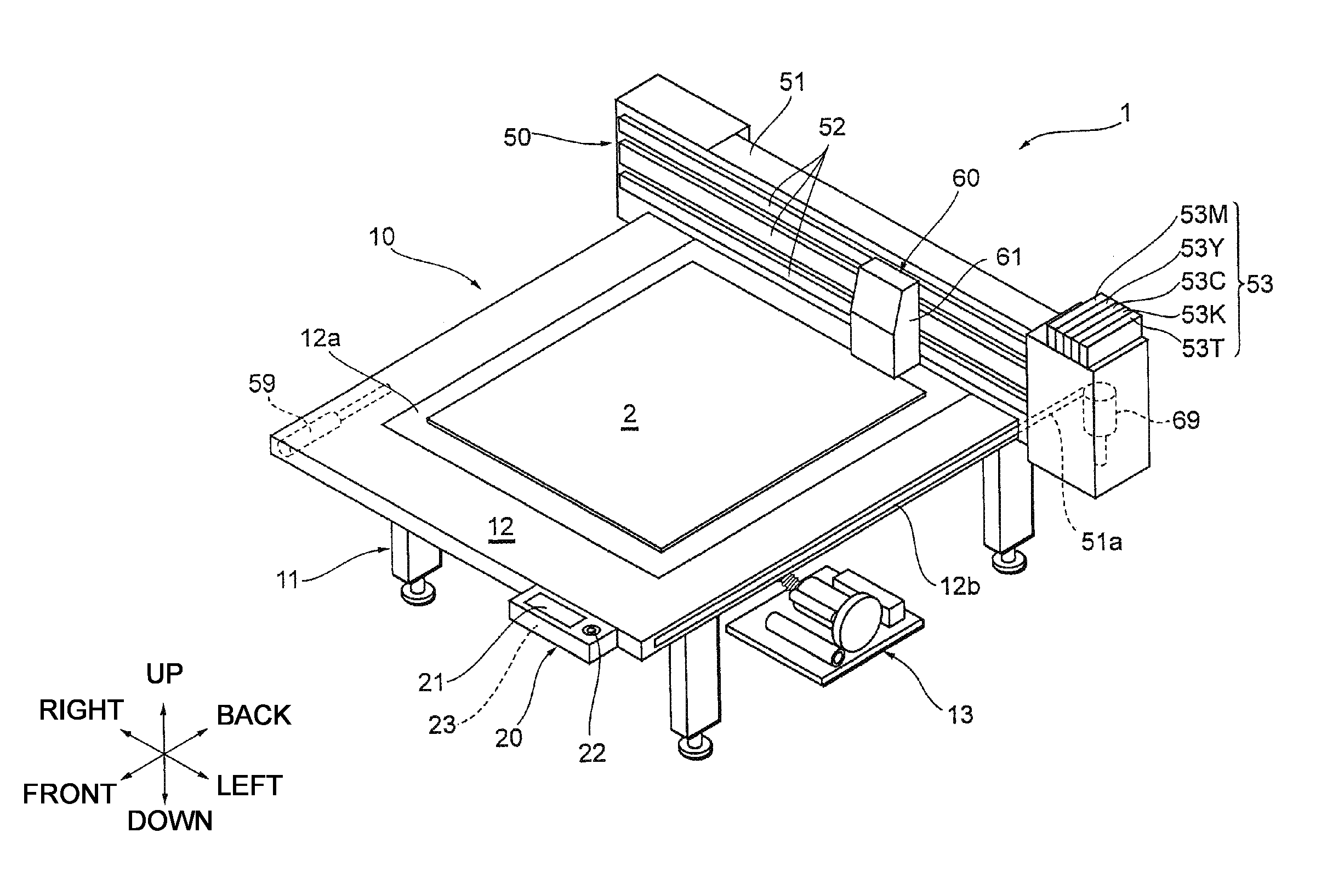
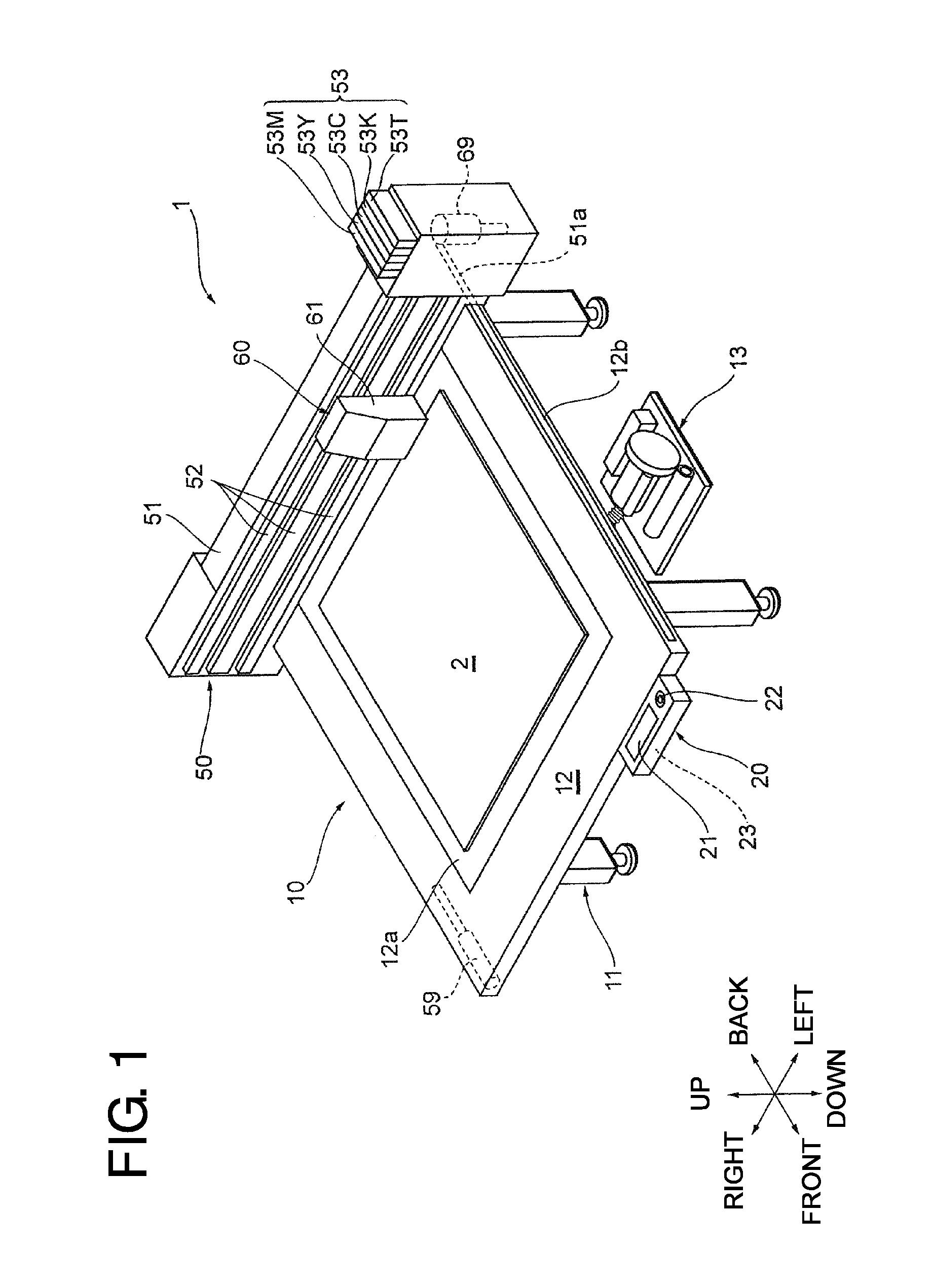
[0035]Embodiments of the present invention will be described hereinafter with reference to the accompanying drawings. In the following description, the constituent elements having substantially the same function and arrangement are denoted by the same reference numerals, and repetitive descriptions will be made only when necessary. The embodiments of the present invention have the following arrangements.

[0036]As an example of an inkjet printer to which the present invention is applied, an inkjet printer 1 which conducts desired printing relative to a print medium by moving a print unit in two perpendicular axial (X-axis Y-axis) directions in a horizontal plane relative to the print medium fixed and held on a table is shown in FIG. 1 in a perspective view taken from oblique front. For the sake of convenience, in FIG. 1, directions indicated by arrows will be forward, backward, leftward, rightward, upward, and downward directions, respectively in the following description.

[0037]The in...


PUM


Abstract

An inkjet printer including a UVLED unit which emits ultraviolet light to a print medium supported on a supporting table to cure UV ink droplets deposited on the print medium. The inkjet printer further includes a controller which adjust the light quantity of ultraviolet light, emitted from the UVLED unit to the UV ink droplets deposited on the print medium, from a light quantity for temporary curing to a light quantity for final curing, and a control unit capable of selecting between a two-stage curing mode in which UV ink droplets deposited on the print medium are temporarily cured ant are then finally cured and a single-stage curing mode in which UV ink droplets are finally cured by an irradiation with ultraviolet light at one time by means of the UVLED unit and the controller.

Description

CROSS-REFERENCE TO RELATED APPLICATION[0001]The present application claims priority under 35 U.S.C. §119 to Japanese Patent Application No. 2008-051424, filed on Feb. 29, 2008, the entire contents of which are herein incorporated by reference.BACKGROUND OF THE INVENTION[0002]1. Field of the Invention[0003]The present invention relates to an inkjet printer.[0004]2. Discussion of the Background[0005]Conventionally, there is known an inkjet printer in which ink is ejected from a print head, which is disposed to face a platen, onto a print medium put on the platen while reciprocating the print head in a left-right direction so as to print the print medium. As one of such inkjet printers, there is a printer of a type ejecting ultraviolet curable ink (hereinafter, referred to as UV ink) having a property that it is cured when irradiated with ultraviolet light. Since the UV ink has excellent weather resistance and excellent water resistance, the UV ink allows printed matters to be used as ...

Claims


Application Information

Patent Timeline
IPC IPC(8): B41J2/14
CPCB41J3/28B41J11/0085B41J11/0065B41J11/002B41J11/00214B41J11/001B41J3/54B41J11/0035B41J19/202B41J15/165C09D11/322B41J11/00212
Inventor HISHIDA, YUKOOHNISHI, MASARUHASHIZUME, HIRONORI
Owner BRAIN WATCH
Learn More