Power Supply Circuit
- Summary
- Abstract
- Description
- Claims
- Application Information
AI Technical Summary
Benefits of technology
Problems solved by technology
Method used
Image

Examples
first embodiment
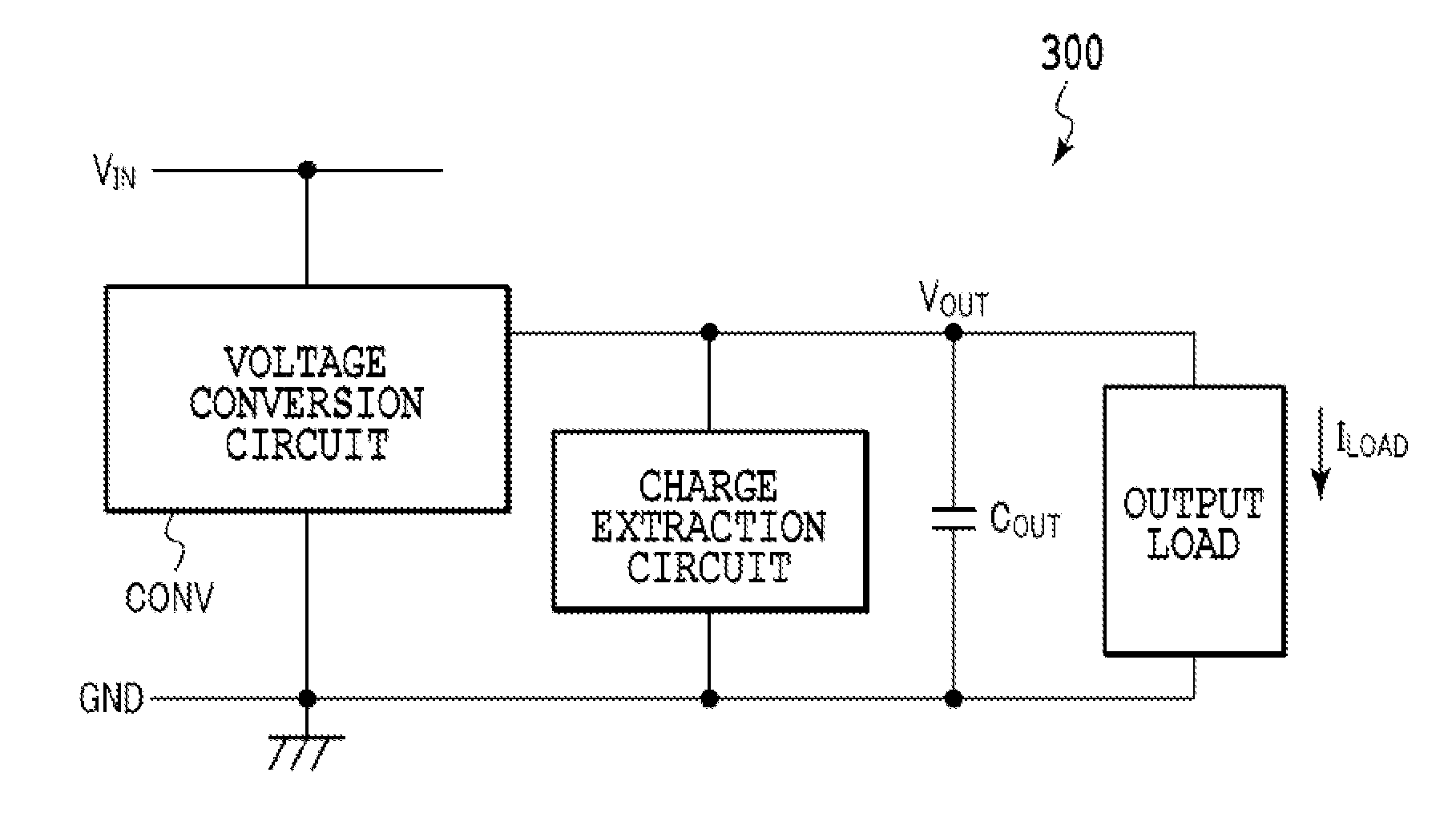
[0042]A power supply circuit according to a first embodiment is shown in FIG. 4. A power supply circuit 400 includes: an inductor L1; a switching device SW1, coupled between an input voltage terminal, to which an input voltage VIN is applied, and the inductor L1; a switching device SW2 coupled between a junction point for the switching device SW1 and the inductor L1 and a ground terminal GND; an output capacitor COUT arranged between an output voltage terminal, from which an output voltage VOUT is to be output, and the ground terminal GND; a charge extraction portion coupled, between the inductor L1 and the output voltage terminal, in parallel to the output capacitor COUT; and a switching device SW3 provided for the charge extraction portion.
[0043]For the power supply circuit 400, a charge extraction circuit is provided by coupling the charge extraction portion and the switching device SW3 in series between the output voltage terminal and the ground terminal. The charge extraction p...
second embodiment
[0045]A power supply circuit according to a second embodiment is shown in FIG. 5. For a power supply circuit 500, a resistor R1 is employed to provide a charge extraction circuit. When the occurrence of overshoot is detected that is a result of a rise in an output voltage VOUT that exceeds a threshold value that has been designated in advance, a switching device SW3 is turned on, and then a current flows through the resistor R1. This current serves as an alternative current used to compensate for the sudden reduction in the load current ILOAD, and can be employed to suppress a current ICAP that is to be supplied to a capacitor COUT, and to halt the rise in the output voltage VOUT.
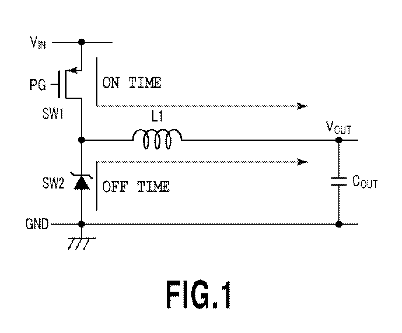
[0046]FIG. 7 is a diagram for explaining an example operation of the power supply circuit according to this embodiment. FIGS. 6A and 6B are diagrams for explaining the operation of the conventional power supply circuit shown in FIG. 1 as a comparison. A change in a load current for the power supply circuit ...
third embodiment
[0056]A power supply circuit according to a third embodiment is shown in FIG. 8. For a power supply circuit 800, a charge extraction portion is provided by using a parallel circuit that includes a resistor R1 and a capacitor C1, which are coupled in parallel. When overshoot is detected as a result of an increase in an output voltage VOUT that exceeds a threshold value designated in advance, a switching device SW3 is turned on, and a current flows through a resistor R1. This current serves as an alternative current used to compensate for a sudden reduction in a load current ILOAD, and can be employed to suppress a current ICAP, which is supplied to an output capacitor COUT, and to halt a rise in the output voltage VOUT. In addition, when the switching device SW3 is turned on, the voltage of the capacitor C1 instantaneously reaches VOUT, which is a level for the ON state of the switching device SW3, so that a charge Q1=C1×VOUT is extracted from the output capacitor COUT, and is suppli...
PUM
 Abstract
Description
Claims
Application Information
 - R&D
- Intellectual Property
- Life Sciences
- Materials
- Tech Scout
- Unparalleled Data Quality
- Higher Quality Content
- 60% Fewer Hallucinations
Browse by: Latest US Patents, China's latest patents, Technical Efficacy Thesaurus, Application Domain, Technology Topic, Popular Technical Reports.
© 2025 PatSnap. All rights reserved.Legal|Privacy policy|Modern Slavery Act Transparency Statement|Sitemap|About US| Contact US: help@patsnap.com