Camera module and method of manufacturing the same
Inactive Publication Date: 2011-03-08
SAMSUNG ELECTRO MECHANICS CO LTD
View PDF5 Cites 2 Cited by
Summary
Abstract
Description
Claims
Application Information
AI Technical Summary
This helps you quickly interpret patents by identifying the three key elements:
Problems solved by technology
Method used
Benefits of technology
Benefits of technology
[0020]An advantage of the present invention is that it provides a camera module which adopts a holder assembly which has an image sensor and an IR filter mounted therein and is formed of a ceramic material, thereby minimizing defects caused by foreign matters. Since the holder assembly is previously manufactured, it is possible to quickly respond to users' requests. Further, as a reflow process is adopted, it is possible to simplify the manufacturing process. Further, when defects occur in the camera module, a rework operation can be easily performed, and the manufacturing cost can be reduced.
[0021]Another advantage of the invention is that it provides a method of manufacturing a camera module.
[0022]Additional aspect and advantages of the present general inventive concept will be set forth in part in the description which follows and, in part, will be obvious from the description, or may be learned by practice of the general inventive concept.
[0023]According to an aspect of the invention, there is provided a method of manufacturing a camera module, the camera module including a housing that includes one or more lenses which are sequentially fixed and coupled and of which the focus does not need to be adjusted; a holder assembly that is coupled to a lower end portion of the housing; and a main substrate that is coupled to a lower end portion of the holder assembly. The method comprises providing bonding media for bonding the main substrate through a reflow process such that the bonding media are disposed on a lower surface of a holder substrate composing the lower end portion of the holder assembly, and fixing an image sensor on an upper surface of the holder substrate through wire bonding; mounting a holder formed of a ceramic material so as to surround the image sensor wire-bonded to the holder substrate; mounting an IR filter on the holder so as to seal an internal space of the holder, which is defined by the holder substrate and the holder and in which the image sensor is included, thereby completely manufacturing the holder assembly; bonding the holder assembly to the main substrate through a reflow process; and performing fine focus adjustment while sliding the housing into the housing mounting portion formed at the upper end portion of the holder body coupled to the main substrate.
[0024]The housing may include a support portion which extends from an inner lower end of the housing so as to come in contact with the upper end portion of the holder assembly. The support portion may be provided so as to be disposed on an upper end portion of the IR filter.
[0025]The method further comprises providing passive elements on the holder substrate such that the passive elements are positioned outside the holder, before the bonding of the holder assembly to the main substrate.
Problems solved by technology
Then, foreign matters such as minute particles may occur, thereby degrading the assembling property.
Method used
Image
Click on the blue label to locate the original text in one second.
Reading with bidirectional positioning of images and text.
Examples
first embodiment
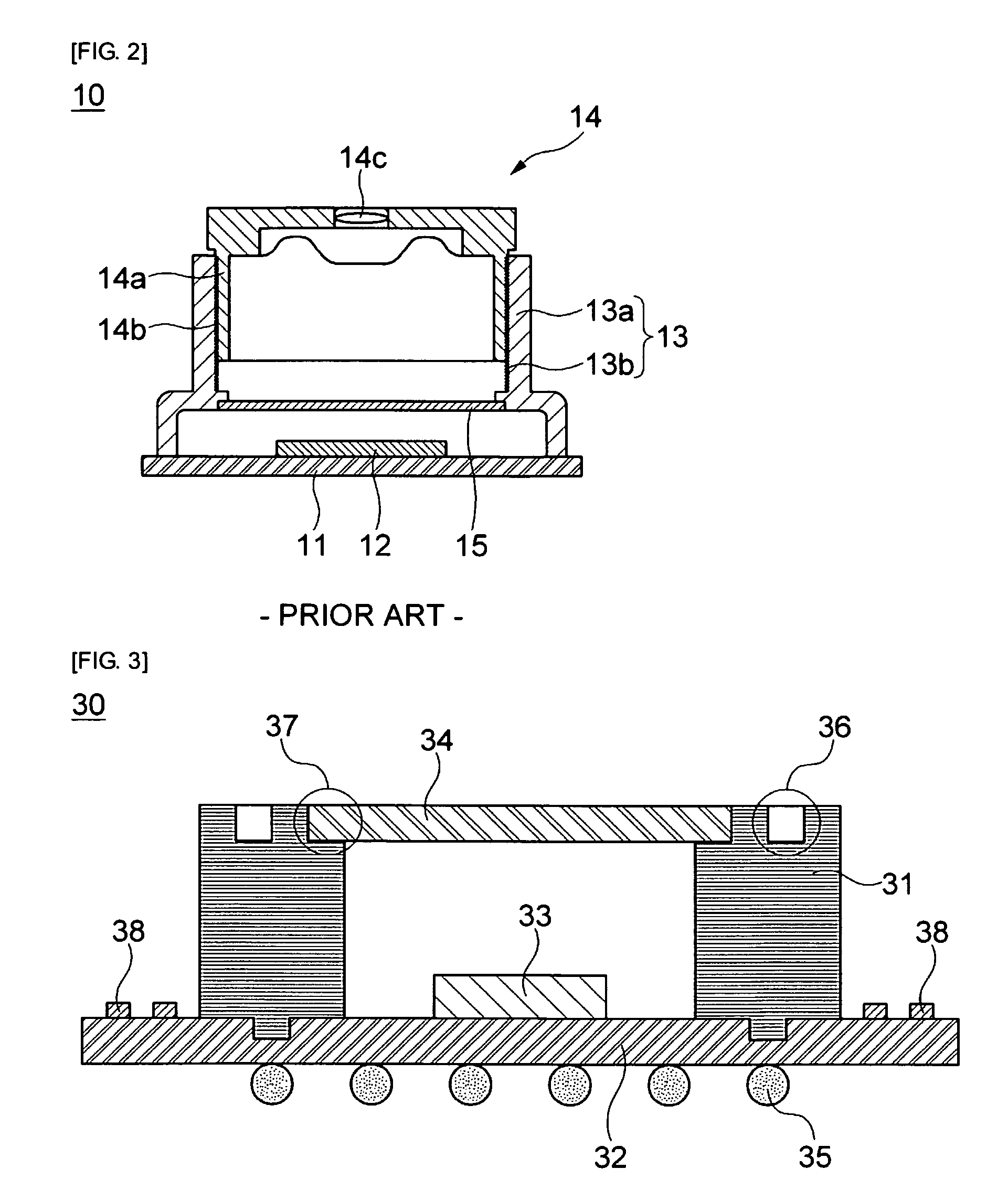
[0042]FIG. 3 is a cross-sectional view of a holder assembly according to a first embodiment of the invention.
[0043]The hold assembly 30 shown in FIG. 3 includes a holder 31, a holder substrate 32, an image sensor 33, an IR filter 34, and bonding media 35 for a reflow process.
[0044]First, the holder 31 formed in a cylindrical shape is mounted so as to surround the image sensor 33 fixed on the holder substrate 32 through wire bonding. In the first embodiment, when a housing (not shown in FIG. 3) including a lens is coupled to the holder assembly 30, a lower end portion of the housing and an upper end portion of the holder assembly 30 are coupled in a sliding manner. Therefore, a housing mounting portion 36 is formed along the circumferential surface of the upper end of the holder 31.
[0045]Further, a stepped filter mounting portion 37 is formed along the inner circumferential surface of the upper end of the holder 31, and the IR filter 34 is mounted on the filter mounting portion 37. F...
second embodiment
[0054]FIG. 4 is a cross-sectional view of a camera module 40 according to a second embodiment of the invention.
[0055]In this embodiment, the descriptions of the same technical construction as that of the first embodiment will be omitted, and like reference numerals will be attached to the same components.
[0056]The camera module 40 according to the second embodiment includes a main substrate, a housing 42, and the holder assembly 30 described in the first embodiment.
[0057]First, the holder assembly 30 is mounted on the main substrate 41, and a reflow process is then performed. In general, since the reflow process is performed at a high temperature of about 250° C., the reflow process is performed before the housing formed of plastic such as PVC is mounted on the holder assembly 30.
[0058]After the holder assembly 30 is bonded to the main substrate 41, the housing 42 is mounted on the upper end portion of the holder assembly 30. The housing 42 includes one or more lenses 42a which are ...
third embodiment
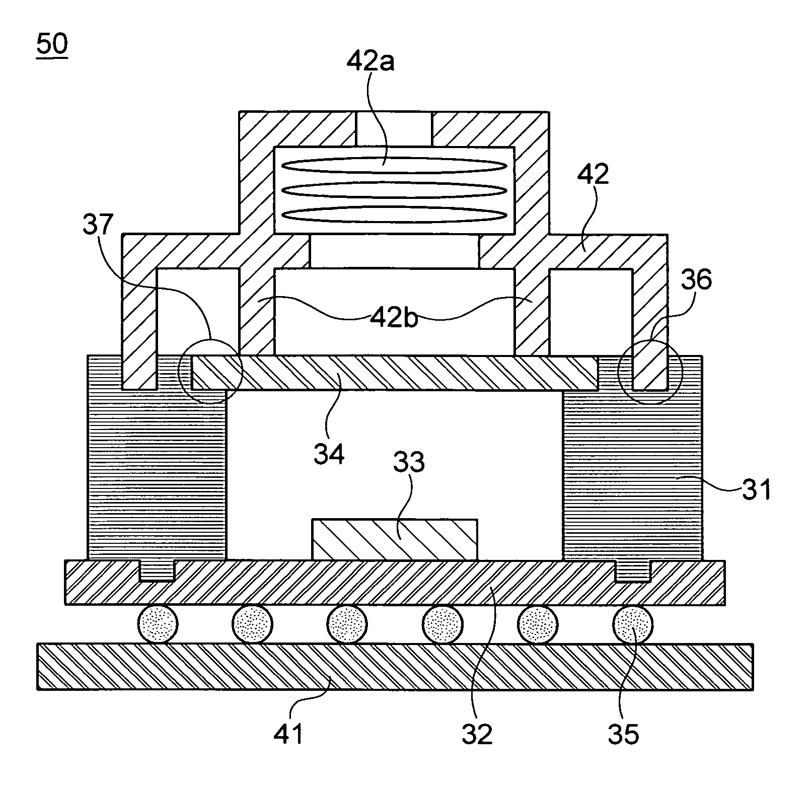
[0060]FIG. 5 is a cross-sectional view of a camera module 50 according to a third embodiment of the present invention.
[0061]In this embodiment, the descriptions of the same technical construction as those of the first and second embodiments will be omitted, and like reference numerals will be attached to the same components.
[0062]The housing 42 further includes a support portion 42b which extends from an inner lower end of the housing 42 so as to come in contact with the upper end of the holder assembly. That is, the housing 42 further includes the cylindrical support portion 42b formed at the inner lower end thereof. The support portion 42b may be disposed on the upper end of the IR filter 34.
[0063]As the support portion 42b is adopted, the housing 42 and the holder assembly 30 can be coupled more reliably. Further, when the housing 42 is coupled, the housing 42 can be inserted into the holder 31 without a separate height adjustment process. In other words, the height of the suppor...
PUM
Abstract
Provided is a method of manufacturing a camera module, the camera module including a housing that includes one or more lenses which are sequentially fixed and coupled and of which the focus does not need to be adjusted; a holder assembly that is coupled to a lower end portion of the housing; and a main substrate that is coupled to a lower end portion of the holder assembly. The method comprises providing bonding media for bonding the main substrate through a reflow process such that the bonding media are disposed on a lower surface of a holder substrate composing the lower end portion of the holder assembly, and fixing an image sensor on an upper surface of the holder substrate through wire bonding; mounting a holder formed of a ceramic material so as to surround the image sensor wire-bonded to the holder substrate; mounting an IR filter on the holder so as to seal an internal space of the holder, which is defined by the holder substrate and the holder and in which the image sensor is included, thereby completely manufacturing the holder assembly; bonding the holder assembly to the main substrate through a reflow process; and performing fine focus adjustment while sliding the housing into the housing mounting portion formed at the upper end portion of the holder body coupled to the main substrate.
Description
CROSS-REFERENCE TO RELATED APPLICATIONS[0001]This application claims the benefit of Korean Patent Application No. 10-2008-0077148 filed with the Korean Intellectual Property Office on Aug. 6, 2008, the disclosure of which is incorporated herein by reference.BACKGROUND OF THE INVENTION[0002]1. Field of the Invention[0003]The present invention relates to a camera module and a method of manufacturing the same.[0004]2. Description of the Related Art[0005]Recently, camera modules are mounted on IT devices such as mobile terminals, PDAs (Personal Digital Assistant), MP3 players and so on. With the development of technology, the resolution of the camera modules changes from 300,000 pixels (VGA) to several million pixels, and the reduction in size and thickness of the camera modules are being performed depending on mounting targets. Further, the camera module provides various additional functions, such as auto-focusing (AF) and optical zoom.[0006]The camera modules are manufactured by using...
Claims
Application Information
Patent Timeline
Application Date:The date an application was filed.
Publication Date:The date a patent or application was officially published.
First Publication Date:The earliest publication date of a patent with the same application number.
Issue Date:Publication date of the patent grant document.
PCT Entry Date:The Entry date of PCT National Phase.
Estimated Expiry Date:The statutory expiry date of a patent right according to the Patent Law, and it is the longest term of protection that the patent right can achieve without the termination of the patent right due to other reasons(Term extension factor has been taken into account ).
Invalid Date:Actual expiry date is based on effective date or publication date of legal transaction data of invalid patent.

