Continuous mixer and mixing method

a continuous mixer and mixing method technology, applied in the direction of mixing, rotary stirring mixers, transportation and packaging, etc., can solve the problems of large shear deformation (tearing direction deformation) in the material, insufficient mixing, and inability to give the amount of deformation necessary for dispersion to the dispersed phase, etc., to achieve reliable and efficient mixing

Active Publication Date: 2013-06-27
KOBE STEEL LTD
View PDF9 Cites 7 Cited by
  • Summary
  • Abstract
  • Description
  • Claims
  • Application Information

AI Technical Summary

Benefits of technology

[0010]The present invention has been developed in view of the above problems, and an object thereof is to provide a continuous mixer and a mixing method capable of reliably and efficiently mixing even a material having a large viscosity difference between a dispersed phase and a matrix phase therein.

Problems solved by technology

In this clearance between the mixing rotors, the outer peripheral surface (wall surface of the tip) of one mixing rotor and the outer peripheral surface (wall surface of the tip) of the other mixing rotor move in mutually different directions, thereby causing a great shear deformation (deformation in a tearing direction) in the material.
However, it has become apparent that composite resin materials and mixing resistant polymer alloys in which a filler being developed in recent years and having a strong cohesive force is mixed and materials which require reliable dispersion or destruction of a gel cannot be sufficiently mixed by only a large shear force.
For example, a shear force applied to the material is expended to rotate the dispersed phase in a matrix, which makes it impossible to give a deformation amount necessary for dispersion to the dispersed phase.
In short, such a mixing resistant material does not permit mixing energy applied to the material to be efficiently expended for mixing.
If an operating condition and a screw shape are changed to enable the dispersed phase to be effectively dispersed in addition to being given a large shear force, the shear force will causes in the material a heat which can bring the material into thermal deterioration.
This is undesirable because of environmental and economical loss.

Method used


Image

  • Continuous mixer and mixing method
  • Continuous mixer and mixing method
  • Continuous mixer and mixing method

Examples


examples

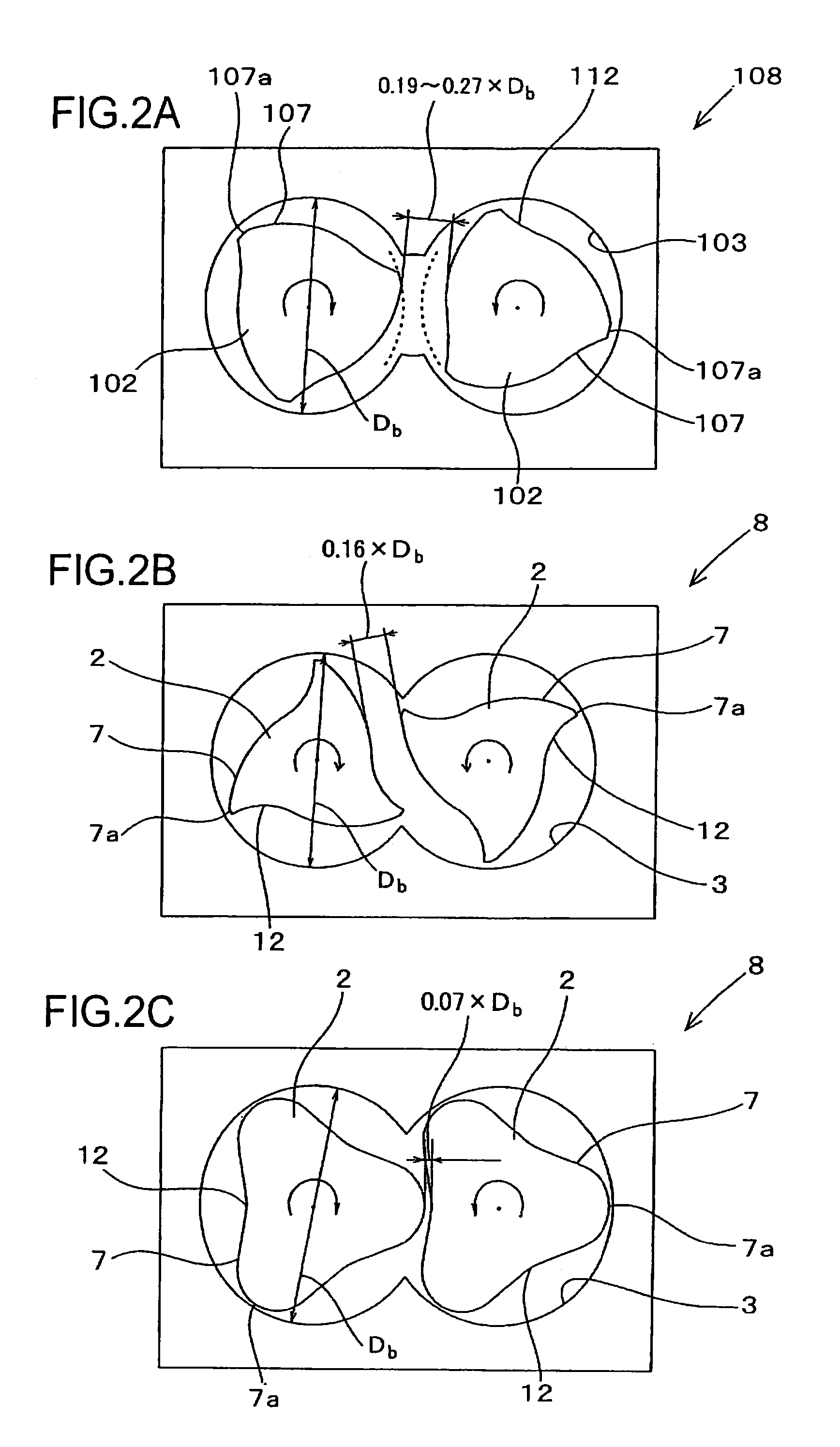
[0076]The conventional example, the first example and the second example respectively shown in FIGS. 2A, 2B and 2C are described in more detail below.

[0077]First, the conventional mixer shown in FIG. 2A includes the barrel 103 having an inner diameter Db of 50 mm and a pair of mixing rotors 102 to be inserted into this barrel 103, the mixing rotors 102 being arranged so as to make the center distance therebetween be 50 mm. Each of the mixing rotors 102 includes an intermediate part in the axial direction which constitutes the mixing portion 108. Each of the mixing portions 108 includes three mixing flights 107 formed about the axial center of the mixing portion 108, and the inter-rotor clearance CR is formed between the both mixing portions 108, 108. In this conventional mixer, the mixing rotors 102 rotate in mutually different directions and the inter-rotor clearance CR varies within the range of 0.19 to 0.26-fold of the inner diameter of the barrel 103 during one rotation of each ...


PUM

PropertyMeasurementUnit
rotation angleaaaaaaaaaa

Abstract

A continuous mixer includes a barrel with a hollow interior, and a pair of mixing rotors housed in the barrel and that rotate in mutually different directions, each mixing rotor including a mixing portion with plural mixing flights formed about an axial center of the mixing rotor and projecting radially outward. The mixing rotors have a center distance therebetween smaller than a rotation outer diameter of each of the respective mixing flights. An inter-rotor clearance, which is the smallest clearance between the mixing portions at each rotation phase of the mixing rotors in a cross section perpendicular to axial directions of the both mixing rotors, has a dimension allowing an extensional flow to be generated in a material passing through the inter-rotor clearance. The continuous mixer can reliably and efficiently mix a material having a large viscosity difference between a dispersed phase and a matrix phase.

Description

TECHNICAL FIELD[0001]The present invention relates to a continuous mixer and a mixing method for mixing a resin material using mixing rotors which rotate in mutually different directions.BACKGROUND ART[0002]Generally, a continuous mixer including a barrel into which a material such as polymer resin pellets and a powdered additive are supplied; and a pair of mixing rotors inserted into this barrel, feeds the material to a downstream side while mixing the material between mixing portions respectively provided in these mixing rotors.[0003]In recent years, the development of new composite resin materials and the like has increased the number of kinds of materials to be mixed and needs for the continuous mixers to perform improved mixing. Such needs include, for example, uniform dispersion or diffusion of a filler, an additive and the like in a material, an improvement in the dispersion structure of a polymer alloy, an improvement in reaction homogeneity at the time of reactive extrusion...

Claims


Application Information

Patent Timeline
Patent Type & Authority Applications(United States)
IPC IPC(8): B29B7/46B29C48/40B29C48/655B29C48/67B29C48/92
CPCB29B7/482B29B7/46B29C47/92B29C47/64B29B7/489B29C47/627B29C48/655B29C48/67B29B7/465B29B7/488B29C48/40B29B7/48B01F27/72
Inventor YAMAGUCHI, KAZUOUDA, TAKAYAKURODA, YOSHINORIFUKUI, TSUGUSHI
Owner KOBE STEEL LTD
Why Eureka
Try Eureka