

Sound output device
a sound output device and sound output technology, applied in the direction of transducer details, instruments, communication jamming, etc., can solve the problems of reducing the sound pressure level of operation sounds, not solving problems completely, and reducing the masking
- Summary
- Abstract
- Description
- Claims
- Application Information
AI Technical Summary
Benefits of technology
Problems solved by technology
Method used
Image

Examples
embodiment
Actions and Effects of Embodiment
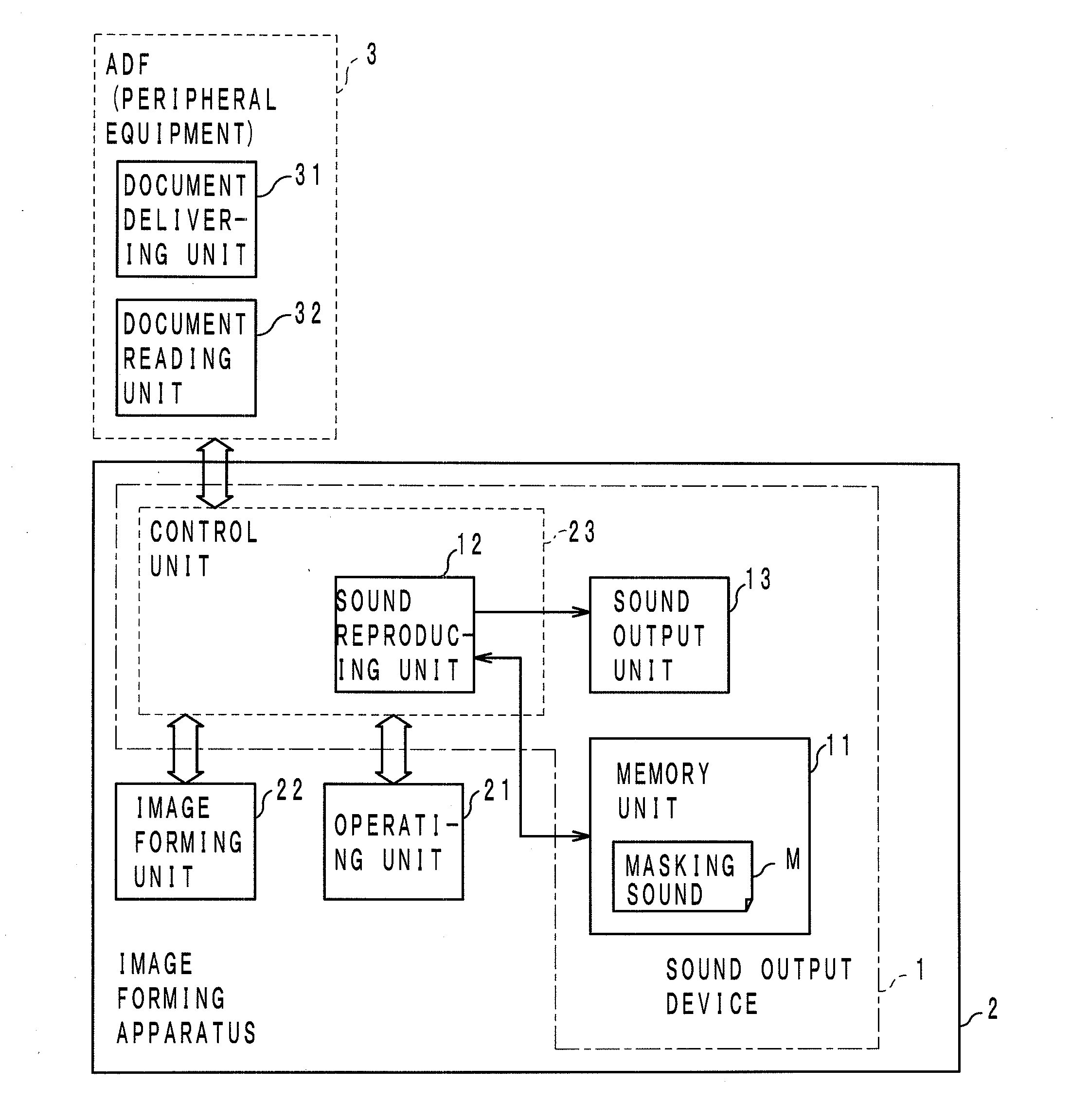
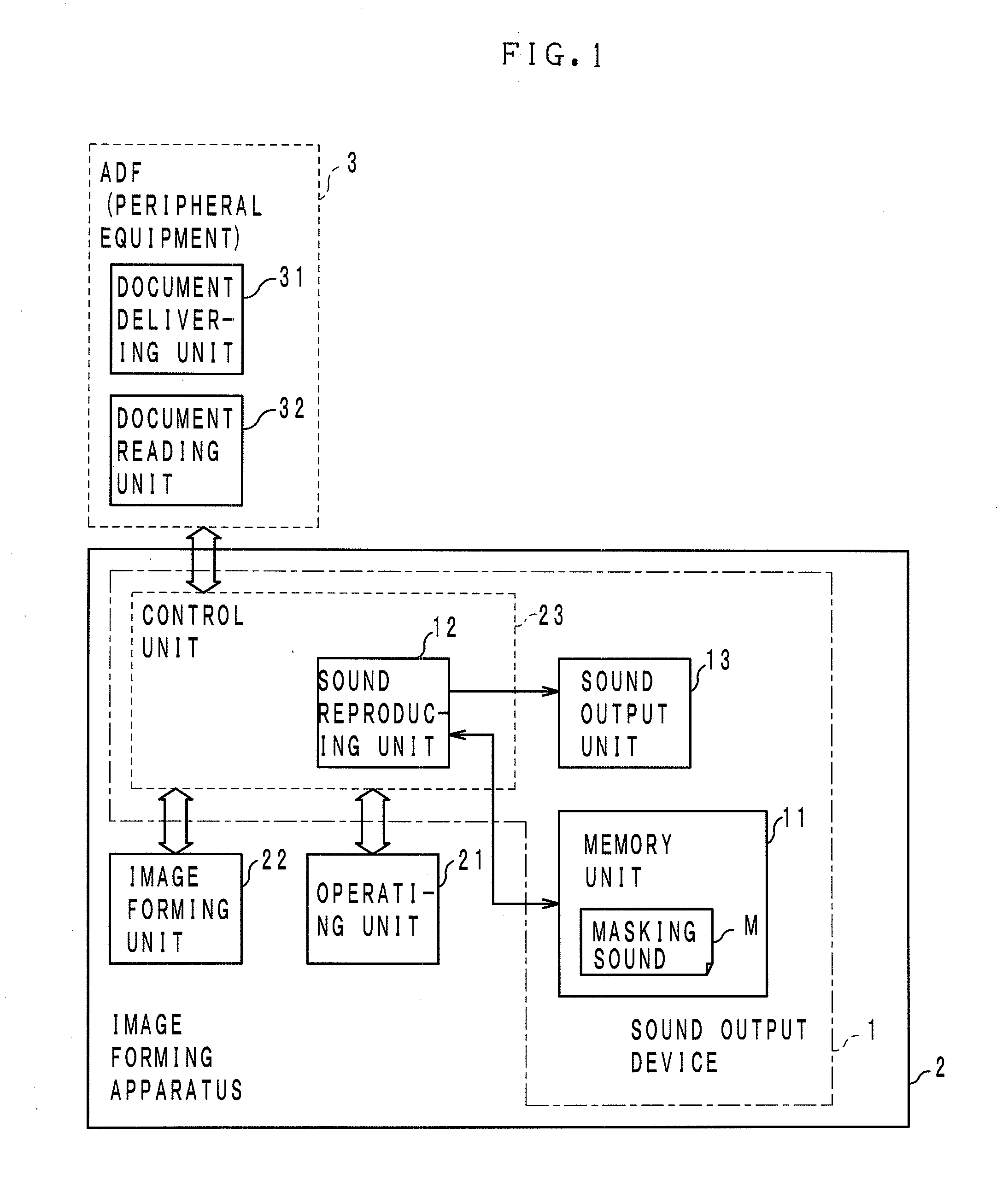
[0032]As described above, in the embodiment of the present invention, the memory unit 11 has the pre-created masking sound M stored therein. After the image forming apparatus 2 receives image data but before it starts printing processing, the sound reproducing unit 12 reads and reproduces the masking sound M from the memory unit 11 and causes the sound output unit 13 to output the reproduced sound. In this manner, the masking sound M is outputted prior to the printing processing by the image forming apparatus 2, and therefore the user's attention is drawn by the masking sound M being outputted first. Therefore, the user's attention tends to not be directed toward the operation sound to be outputted thereafter. Thus, it is possible to provide the sound output device 1 that better achieves a masking effect.
[0033]Further, while the masking sound M masks the operation sound (noise) produced at a high sound pressure level during a predetermined action, i....
first modification
[0035]Incidentally, the image forming apparatus 2 can idle in a plurality of modes, including sleep mode, power saving mode, standby mode, etc. The time (T2−T1) from image data reception until the start of recording medium supply varies among the idling modes. To change the output sound pressure level of the masking sound M from the initial value to the standard value in the period from time T1 to time T2, the sound reproducing unit 12 preferably changes the timing of outputting the masking sound M, in accordance with the idling mode at the time of image data reception. For example, upon reception of image data in sleep mode, the sound reproducing unit 12 starts outputting the masking sound M some seconds t1 before time T2, as shown in FIG. 4. Moreover, in the case of power saving mode or standby mode, the sound reproducing unit 12 starts outputting the masking sound M some seconds t2 or t3 before time T2. Here, in the present embodiment, t1, t2, and t3 satisfy t1>t2>t3.
[0036]In thi...
second modification
[0037]In the first modification, the timing of starting output of the masking sound M and the degree of change in the output sound pressure level of the masking sound M per unit time are adjusted for each of the idling modes. However, this is not restrictive, and, for example, the timing of starting output of the masking sound M may be fixed for any of the idling modes, as shown in FIG. 5. For example, in the example of FIG. 5, image data is received at time T0, and output of the masking sound M starts 0.2 seconds later at time T1′. For example, the sound pressure level of the masking sound M is adjusted so as to reach the standard value at time T2, 1.5 seconds after time T1′. In this case, for each idling mode, the control unit 23 adjusts the timing of starting preparations for printing and the timing of starting recording medium supply, such that a masking effect can be produced at time T2 regardless of the idling mode. The image forming apparatus 2 adopts such a mode in which the...
PUM
 Abstract
Description
Claims
Application Information