Bone conduction speaker and compound vibration device thereof

a bone conduction speaker and vibration device technology, applied in the direction of transducer details, electrical transducers, earpiece/earphone attachments, etc., can solve the problems of limited tone quality and difficult to improve the tone quality of current bone conduction speakers containing current vibration devices, and achieve the effect of low cos

Active Publication Date: 2013-06-27
SHENZHEN VOXTECH CO LTD
View PDF4 Cites 81 Cited by
  • Summary
  • Abstract
  • Description
  • Claims
  • Application Information

AI Technical Summary

Benefits of technology

[0005]The purpose of the present invention is providing a bone conduction speaker and its compound vibration device, to improve the vibration parts in current bone conduction speakers, using a compound vibration device composed of a vibration board and a vibration conductive plate to improve the frequency response of the bone conduction speaker, making it flatter, thus providing a wider range of acoustic sound.
[0017]The bone conduction speaker and its compound vibration device as mentioned in the present invention, adopting the fixed vibration boards and vibration conductive plates, make the technique simpler with a lower cost. Also, because the two parts in the compound vibration device can adjust low frequency and high frequency areas, the achieved frequency response is flatter and wider, the possible problems like abrupt frequency responses or feeble sound caused by single vibration device will be avoided.

Problems solved by technology

However, the current bone conduction speakers, with their frequency response curves shown as FIG. 4, have overtopped resonance peaks either in low frequency area or high frequency area, which has limited its tone quality a lot.
Thus, it is very hard to improve the tone quality of current bone conduction speakers containing current vibration devices.

Method used


Image

  • Bone conduction speaker and compound vibration device thereof
  • Bone conduction speaker and compound vibration device thereof
  • Bone conduction speaker and compound vibration device thereof

Examples


Embodiment Construction

[0024]A detailed description of the implements of the present invention is stated here, together with attached figures.

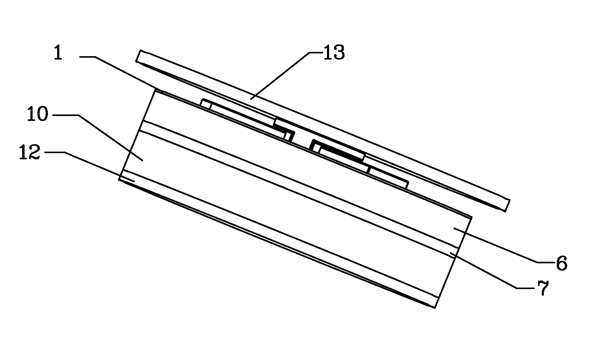
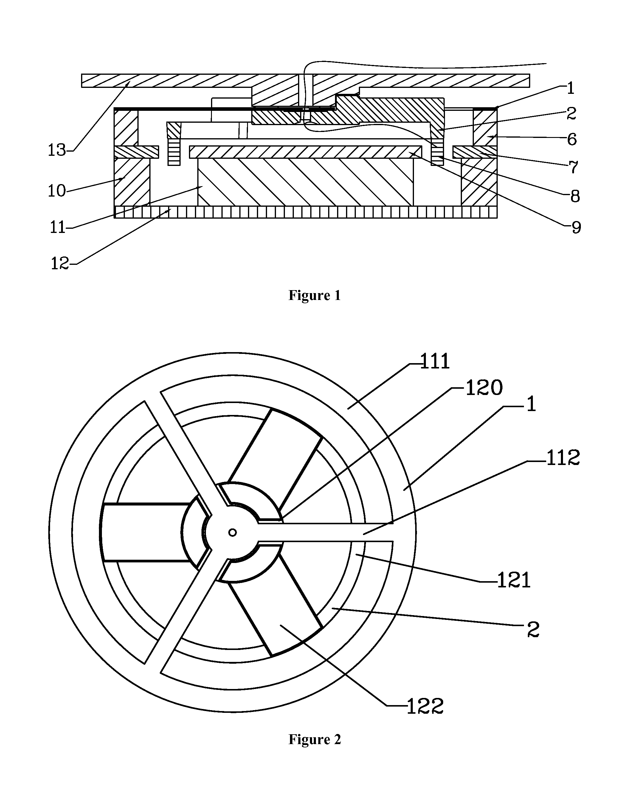
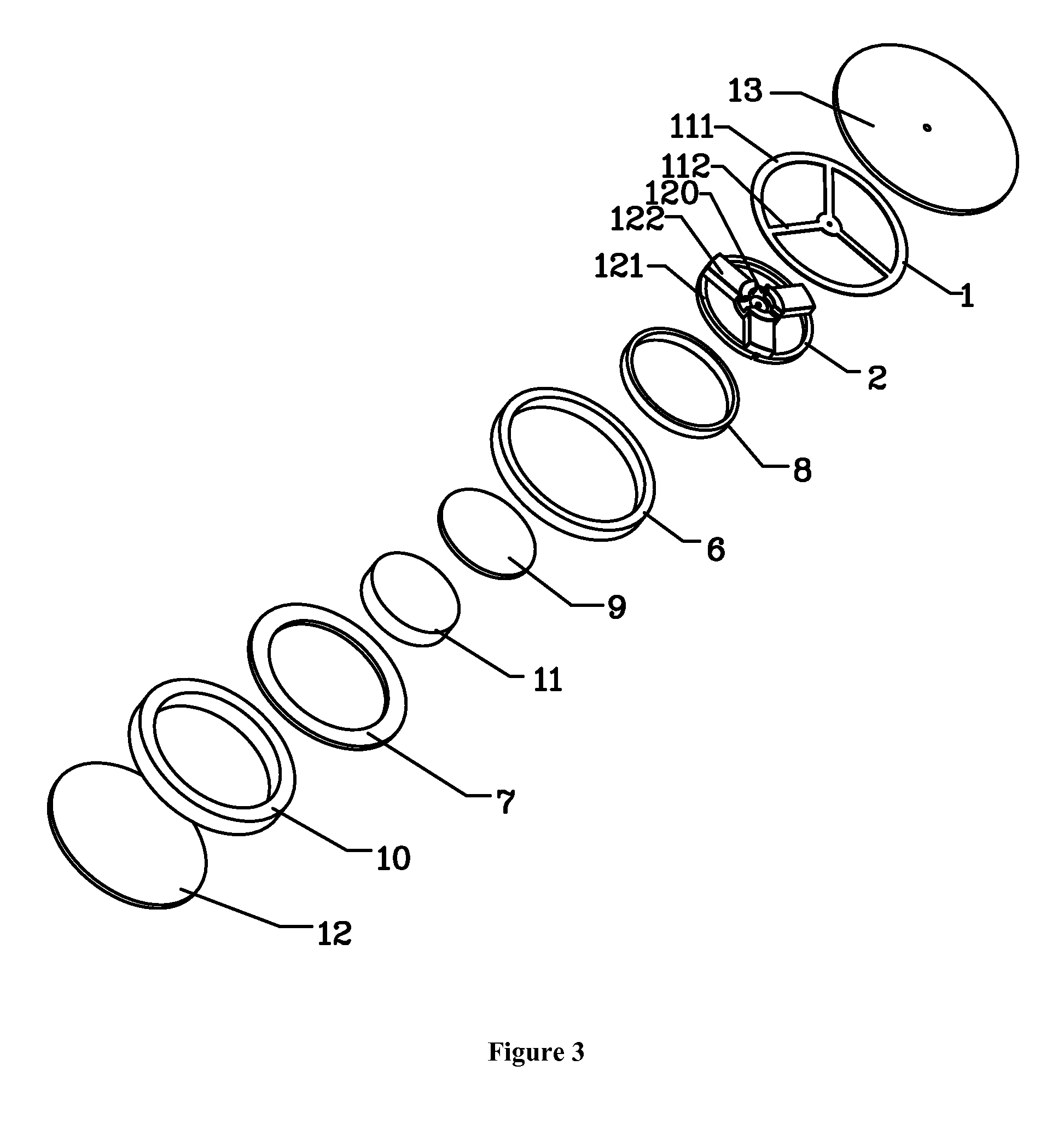
[0025]As shown in FIG. 1 and FIG. 3, the compound vibration device in the present invention of bone conduction speaker, comprises: the compound vibration parts composed of vibration conductive plate 1 and vibration board 2, the vibration conductive plate 1 is set as the first torus 111 and three first rods 112 in the first torus converging to the center of the torus, the converging center is fixed with the center of the vibration board 2. The center of the vibration board 2 is an indentation 120, which matches the converging center and the first rods. The vibration board 2 contains a second torus 121, which has a smaller radius than the vibration conductive plate 1, as well as three second rods 122, which is thicker and wider than the first rods 112. The first rods 112 and the second rods 122 are staggered, present but not limited to an angle of 60 degrees, as shown...


PUM


Abstract

The present invention relates to a bone conduction speaker and its compound vibration device. The compound vibration device comprises a vibration conductive plate and a vibration board, the vibration conductive plate is set to be the first torus, where at least two first rods inside it converge to its center; the vibration board is set as the second torus, where at least two second rods inside it converge to its center. The vibration conductive plate is fixed with the vibration board; the first torus is fixed on a magnetic system, and the second torus comprises a fixed voice coil, which is driven by the magnetic system. The bone conduction speaker in the present invention and its compound vibration device adopt the fixed vibration conductive plate and vibration board, making the technique simpler with a lower cost; because the two adjustable parts in the compound vibration device can adjust both low frequency and high frequency area, the frequency response obtained is flatter and the sound is broader.

Description

FIELD OF THE INVENTION[0001]The present invention relates to improvements on a bone conduction speaker and its components, in detail, relates to a bone conduction speaker and its compound vibration device, while the frequency response of the bone conduction speaker has been improved by the compound vibration device, which is composed of vibration boards and vibration conductive plates.BACKGROUND OF THE INVENTION[0002]Based on the current technology, the principle that we can hear sounds is that the vibration transferred through the air in our external acoustic meatus, reaches to the ear drum, and the vibration in the ear drum drives our auditory nerves, makes us feel the acoustic vibrations. The current bone conduction speakers are transferring vibrations through our skin, subcutaneous tissues and bones to our auditory nerves, making us hear the sounds.[0003]When the current bone conduction speakers are working, with the vibration of the vibration board, the shell body, fixing the v...

Claims


Application Information

Patent Timeline
Patent Type & Authority Applications(United States)
IPC IPC(8): H04R1/00
CPCH04R1/00H04R2460/13H04R31/00H04R1/10H04R9/02H04R9/066H04R25/606H04R9/025H04R9/063
Inventor QI, XINYU, YE
Owner SHENZHEN VOXTECH CO LTD
Why Eureka
Try Eureka