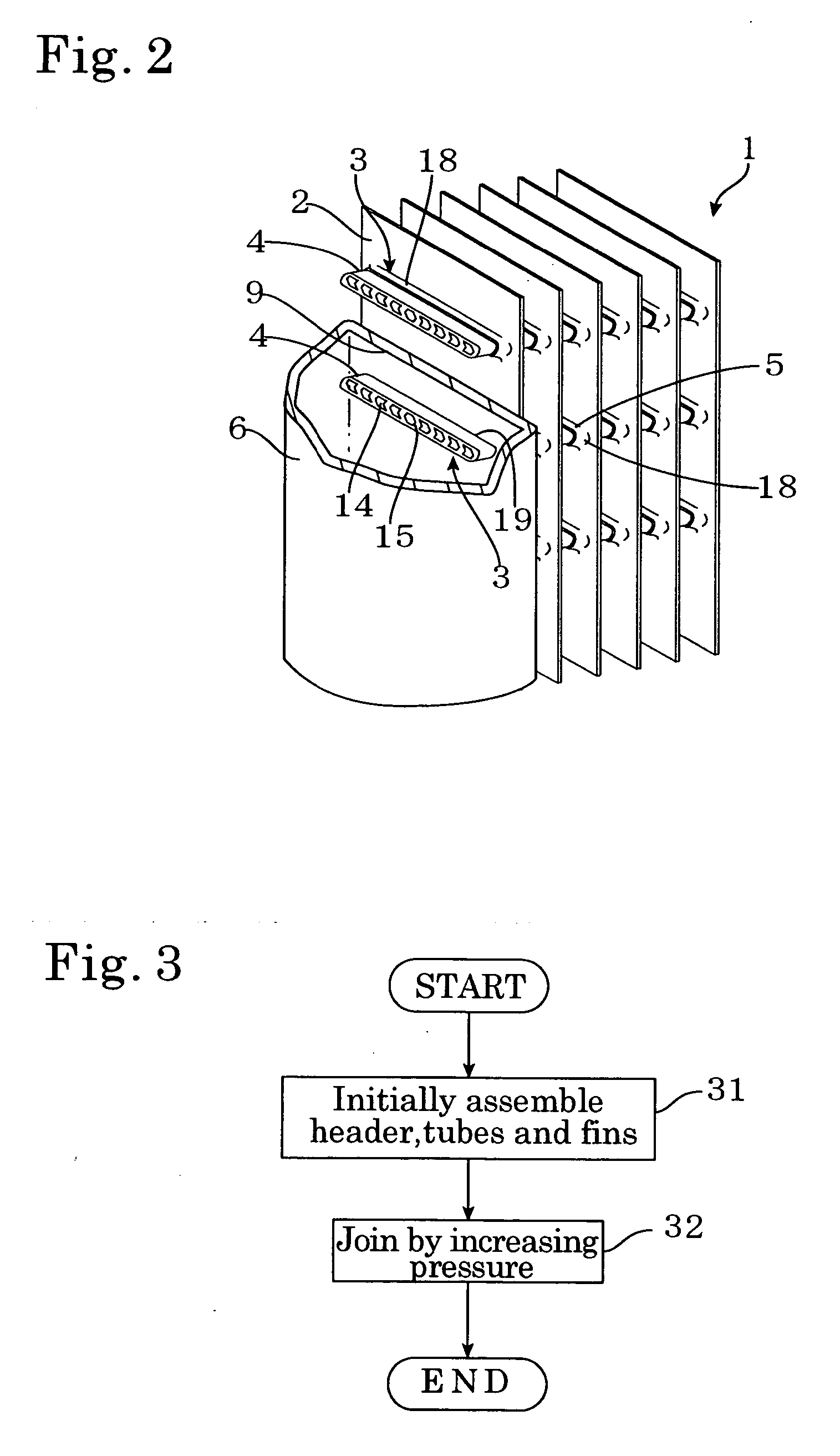
[0010] In the present invention, after flat tubes and fins are assembled, pressure inside the flat tubes is increased using fluid, and by expanding of the flat tubes due to increasing of
internal pressure, the flat tubes and the fins are joined. A method of manufacturing a heat exchanger according to the present invention includes a first step of assembling a flat tube and fins and a second step of increasing an
internal pressure of the flat tube to expand an other part of the flat tube aside from an end part of the flat tube that is attached to a header with respect to the end part in order to make the fins and the other part of flat tube in contact with each other. According to this method of manufacturing, in the first step, flat tubes and fins are assembled so as to pass through the fins, so that a plate fin-type heat exchanger can be manufactured easily.
[0012] For a plate fin-type heat exchanger, an effect of those multi-channel flat tubes can be expanded and joined to the fins in accordance with the invention is so large. Using multi-channel flat tubes that have
high heat exchange efficiency, it is possible to provide, at low cost, a plate fin-type heat exchanger with a
solid construction in which tubes and fins are joined by expansion. According to the present invention, it is possible to provide a heat exchanger with
high heat exchange efficiency as well as high strength. In addition, not limited to the flat tube, since there is no need to insert a tube expander, there is increased flexibility for the arrangement of the tubes that are connected to the fins. For example, even if using no flat tubes, in the prior art, straight tubes for fin contact area and U-shaped connecting pipes for connecting the tubes are used in order to allow an expander to pass through the straight tubes. In this invention, integrated tubes that include straight parts and U-shaped parts can be used and it is possible to make the fins and tubes in contact with each other easily.
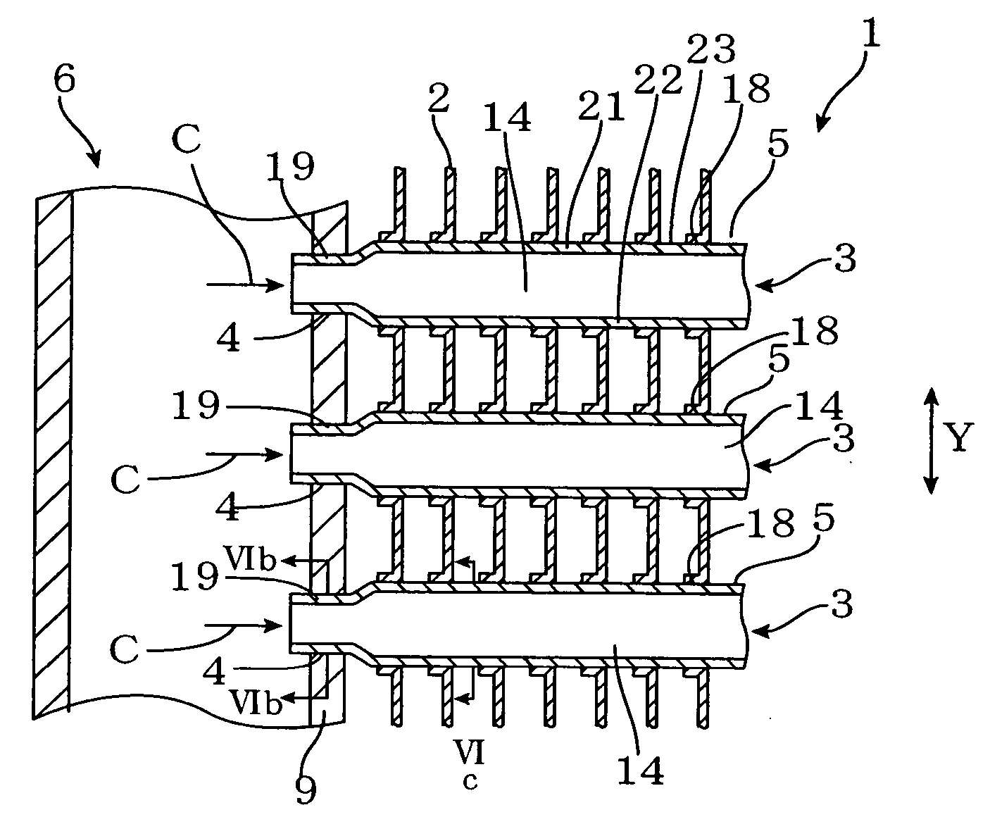
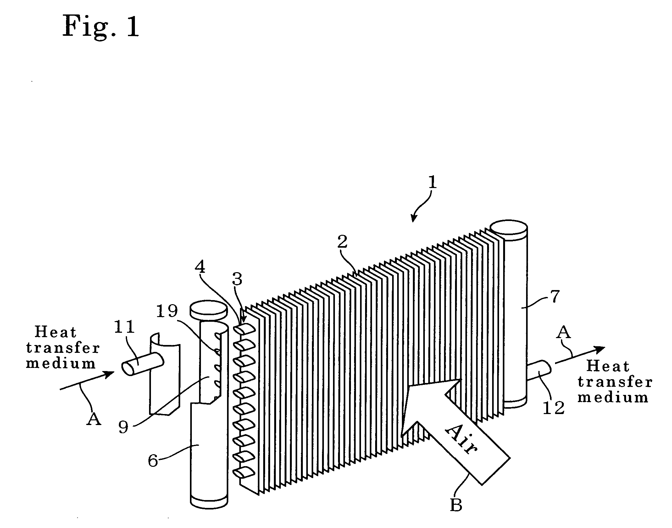
[0013] When an actual plate-fin type or corrugated fin-type heat exchanger is manufactured according to the method of the present invention, it is easiest to apply pressure by introducing a fluid into the flat tubes via a header or headers. In the first step, the end part of the flat tube is mounted to a header, the flat tube and the fins are assembled, and the part where the end part and a header are mounted is sealed. Then, fluid is introduced to increase the internal pressure of the flat tube. In this method, it is not necessary to expand the end part that is attached to the header and it is extremely easy to manufacture a heat exchanger using flat tubes. A heat exchanger manufactured according to this method comprises a flat tube that extends from a header and fins that contact the flat tube, with the other part of the flat tube aside from an end part attached to the header being expanded with respect to the end part. In a plate fin-type heat exchanger, it becomes possible to attach flat tubes by passing the flat tubes through the fins.
[0015] The partitions that are at least partially deformed and placed in a contracted state include partitions that are bent, curved, or inclined. With such partitions, it is possible to smoothly expand the tubes in the minor or sub axis direction of a cross-section thereof, so that the contact
surface pressure between the fins and the flat tubes can easily be kept even. By achieving an even contact
surface pressure around the entire circumference of the flat tubes, the effects of
contact resistance at the contact surfaces between the fins and the flat tubes can be reduced, so that it is possible to provide a heat exchanger with superior heat exchange efficiency.
[0017] In a heat exchanger in which a plurality of flat tubes are attached in a state where the tubes pass through a plurality of plate-like fins in parallel, it is preferable that the flat tubes are attached with a major axis direction of cross-sections thereof in a direction perpendicular to a longitudinal direction of the fins and the tubes are expanded to contact the tubes and the fins each other. The resistance of the flow of external fluid in a direction perpendicular to the flat tubes area becomes little and contact surface area in that direction is increased. Accordingly, a heat exchanger with little pressure loss for external fluid and
high heat exchange efficiency can be provided. In addition, by attaching the flat tubes so that a major axis direction of cross-sections of the tubes is inclined from a direction that is perpendicular to the longitudinal direction of the fins, it is possible to facilitate the downward flow of water droplets adhering to the surfaces of the fins and the flat tubes, so that there is favorable drainage. Accordingly, it is possible to avoid increases in pressure loss for the external fluid due to accumulation of water droplets or
frost formation on upper surfaces of the flat tubes, so that it is possible to provide a heat exchanger with even higher heat exchange efficiency.
[0018] When multi-channel flat tubes and fins are joined by expansion of the tubes, the flat tubes are made larger than the size of burring holes or slits provided in advance in the fins, so that there is the possibility of the fins
springing back after the tubes have been expanded, resulting in the desired contact
surface pressure not being achieved for the fins and the flat tubes. The effects of such
springing back can be avoided by making the partitions positioned at or near a center in a major axis direction of a cross-section of the tubes longer than other partitions. It is also possible to avoid such effects by making parts of openings in the fins for joining or attaching the flat tubes that are faced the center of the flat tubes narrower than other parts of the openings.

