
Method of estimating blur kernel from edge profiles in a blurry image

a blurry image and edge profile technology, applied in image enhancement, image analysis, instruments, etc., can solve the problems of ill-posed problems, blurry and noisy imagery is a ubiquitous problem, and solving sharp images is one of the most computationally demanding methods

Inactive Publication Date: 2013-06-27
NAVY U S A AS REPRESENTED BY THE SEC OF THE THE
View PDF5 Cites 19 Cited by
  • Summary
  • Abstract
  • Description
  • Claims
  • Application Information

AI Technical Summary

Benefits of technology

This patent text describes a method for analyzing blur in images and estimating the blur kernel, which is the function that describes the blurring of the scene in an image. The method uses statistical methods to determine the blurring function and its parameters, which can be used to deblur the image. The method can provide intuitive insights and can be used in real-time video analysis. The blur kernel can be asymmetric, isoplanatic, or anisoplanastic, depending on the scene being captured. Overall, this method allows for effective analysis of blur in images and improves image quality.

Problems solved by technology

Blurry and noisy imagery is a ubiquitous problem for cameras and sensors across the spectrum of applications, including consumer photography, surveillance, computer vision, remote sensing, medical, and astronomical imaging.
Solving for the sharp image is an ill-posed problem because theoretically there can be an infinite set of blur kernel and sharp image pairs that produce the blurry image.
Fergus et al. describes one of the more accurate methods for estimating the blur kernel but it is also one of the most computationally demanding methods.
's method uses only a portion of an image, the solution is highly computationally intensive.
However, in its current implementation the user must provide the edge profile length, which requires a parameter space search since this parameter value affects results.
Their method is slow and is actually an iterative blind deconvolution technique, rather than a blur kernel estimation.
These iterative methods are general, but complex and computationally expensive.

Method used


Image

  • Method of estimating blur kernel from edge profiles in a blurry image
  • Method of estimating blur kernel from edge profiles in a blurry image
  • Method of estimating blur kernel from edge profiles in a blurry image

Examples


Embodiment Construction

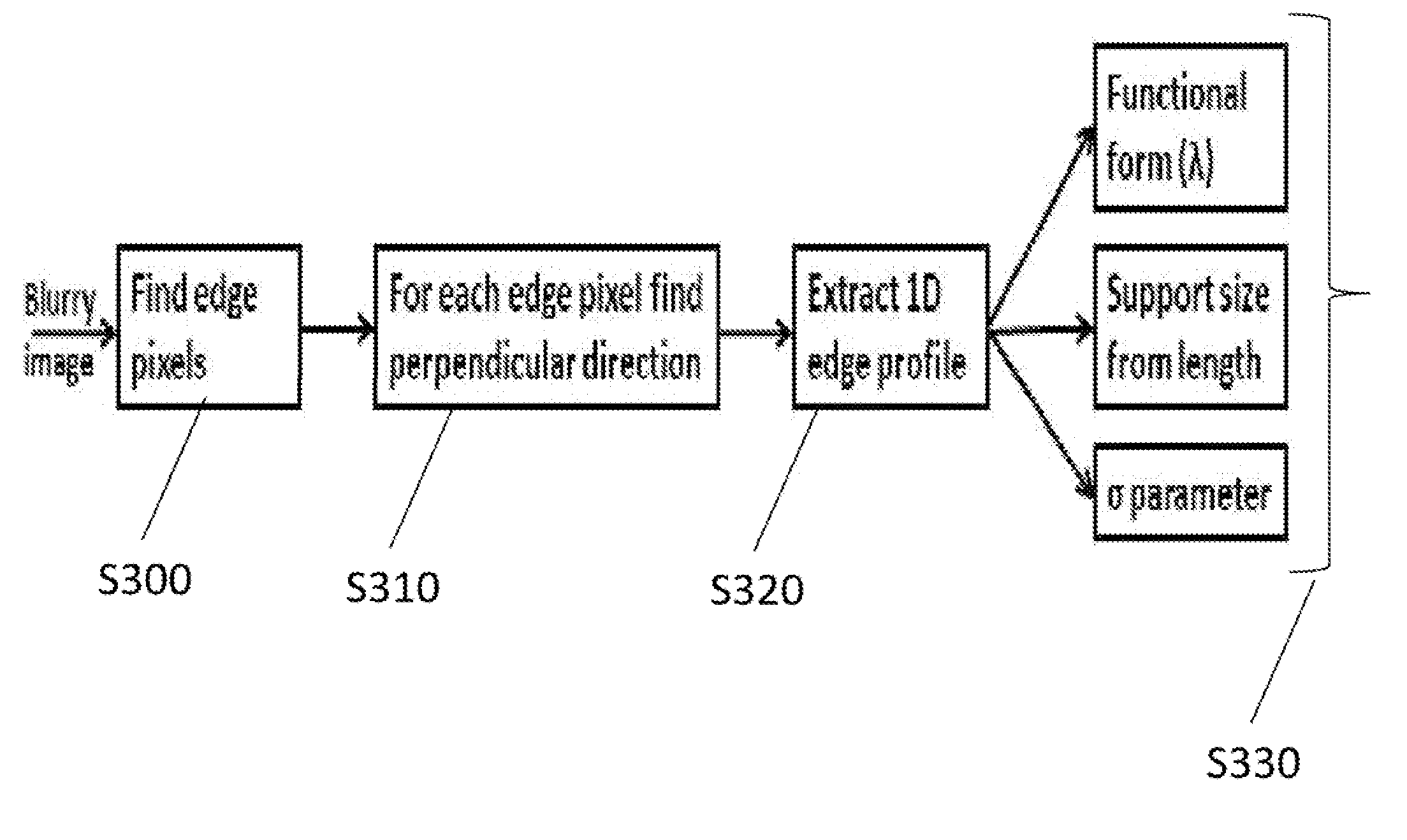
[0023]For edification purposes, it will be helpful to explain the statistical methods to be applied in one or more embodiments of the instant invention to the problem of estimating a blur kernel. These statistical methods are based on the relationships between probability density functions, cumulative distribution functions, and quantile functions. The edge intensity profile is equivalent to the cumulative distribution function. The first step is to determine the statistical model that best fits the data. Probability plot correlation coefficient (“PPCC”) plots allow one to select the blurring functional form that best matches the files of the blurred edges in the image. Given the functional form, the next step is to determine the governing parameters. The slope and intersection of a linear least squares (“LS”) fit to the quantile function values in a probability plot determines the parameters without necessitating a search the parameter space. The slope and the intersection of the L...


PUM


Abstract

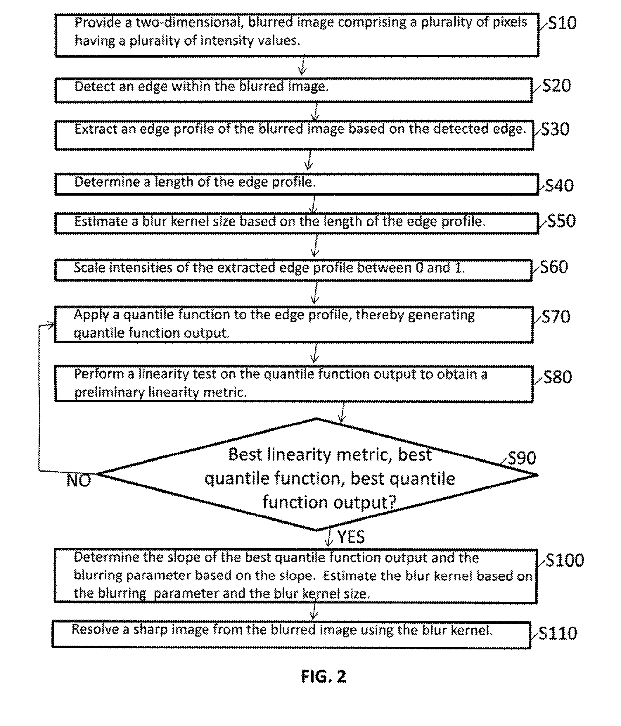
A method of deblurring a two-dimensional, blurred image. An edge within the blurred image is detected, and an edge profile of the blurred image is extracted. A length of the edge profile is determined, and a blur kernel size is estimated based thereon. A preliminary linearity metric is obtained iteratively until a best linearity metric, a best quantile function, and a best quantile function output are determined. A slope of the best quantile function output is determined, and a blurring parameter is determined based thereon. A blur kernel is estimated based on the blurring parameter and the blur kernel size. A sharp image is resolved using the blur kernel.

Description

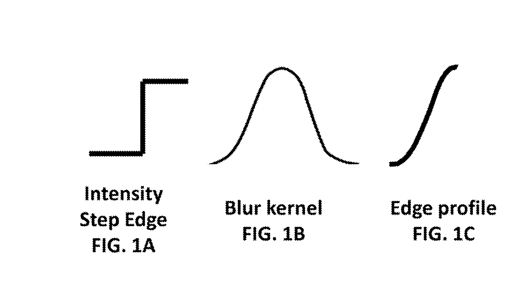
FIELD OF THE INVENTION[0001]The invention relates generally to a method of de-blurring an image, and more particularly to a method of de-blurring an image using analytical computations.BACKGROUND OF THE INVENTION[0002]Blurry and noisy imagery is a ubiquitous problem for cameras and sensors across the spectrum of applications, including consumer photography, surveillance, computer vision, remote sensing, medical, and astronomical imaging. Simple methods to obtain sharp imagery are a valuable asset to all of these applications.[0003]Although there are many sources of image blurring, blurring can be modeled by a single blur kernel, which is also called a point spread function (“PSP”). An equation for describing the observed blurry and noisy image as a function of the underlying sharp image isb=hi+n,   (1)where b is the observed blurry image, h is the blur kernel, is a convolution, i is the sharp image, and n is noise.[0004]As shown, by way of example, in FIGS. 1A-1C, step edges in the...

Claims


Application Information

Patent Timeline
Patent Type & Authority Applications(United States)
IPC IPC(8): G06K9/48
CPCG06T5/003G06T2207/20076G06T5/20G06T5/73
Inventor SMITH, LESLIE N.
Owner NAVY U S A AS REPRESENTED BY THE SEC OF THE THE
Learn More