
Keyboard automatic test method and system using the same

Inactive Publication Date: 2013-06-27
WISTRON CORP
View PDF8 Cites 2 Cited by
  • Summary
  • Abstract
  • Description
  • Claims
  • Application Information

AI Technical Summary

Benefits of technology

The invention is a way to automatically test keyboard functions to save time and reduce costs. This involves using a keyboard automatic test method and system.

Problems solved by technology

However, conventional keyboard tests are faced with issues of increased time and human costs as the keyboards are tested by manually pressing keys of the keyboards.

Method used


Image

  • Keyboard automatic test method and system using the same
  • Keyboard automatic test method and system using the same
  • Keyboard automatic test method and system using the same

Examples


Embodiment Construction

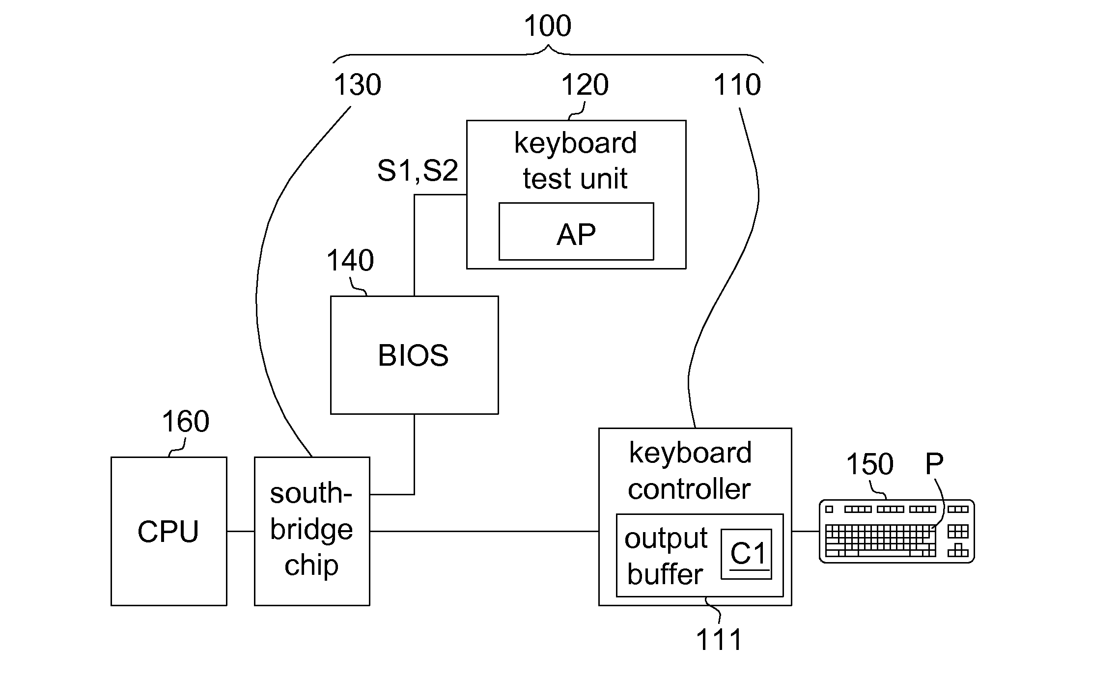
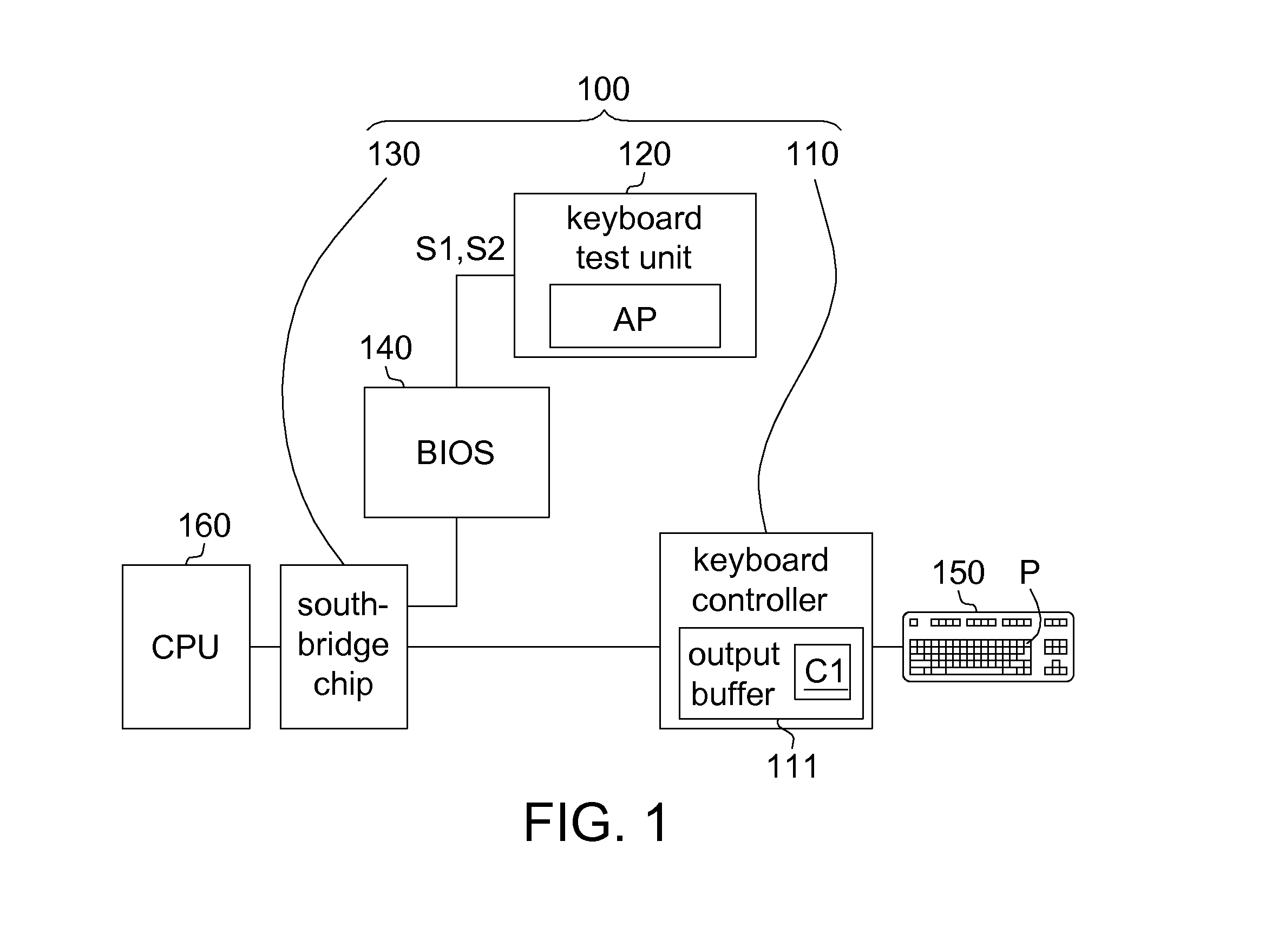
[0015]FIG. 1 shows a block diagram of a keyboard automatic test system according to one embodiment of the present invention. A keyboard automatic test system 100 includes a keyboard controller 110, a keyboard test unit 120, a south-bridge chip 130, a basic input / output system (BIOS) 140 and a central processing unit (CPU) 160.

[0016]Through the south-bridge chip 130, the CPU 160 communicates with the BIOS 140, the keyboard controller 110 and other peripheral elements.

[0017]A code of the BIOS 140 may be preloaded in the south-bridge chip 130 to allow the keyboard controller 110 and the keyboard test unit 120 to communication with the BIOS 140.

[0018]For example, the keyboard test unit 120 is an integrated circuit for executing an application program. Alternatively, the keyboard test unit 120 is firmware. In an embodiment, the keyboard test unit 120 is disposed independently from the CPU 160 (and may be electrically connected). Alternatively, the keyboard test unit 120 is integrated in ...


PUM


Abstract

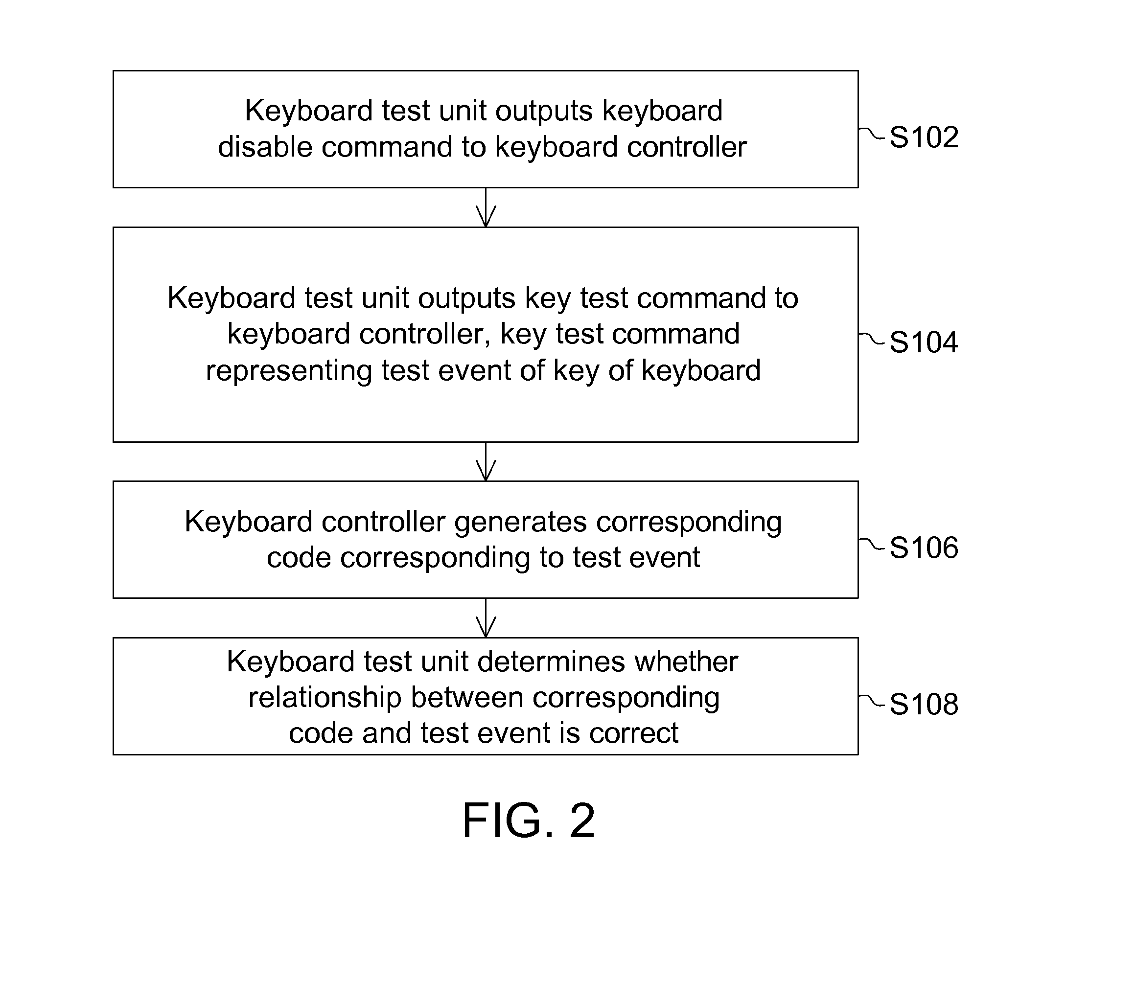
A keyboard automatic test method is provided. A keyboard test unit first outputs a key test command to a keyboard controller. The key test command represents a trigger element of a keyboard is triggered. The keyboard controller generates a corresponding code corresponding to the trigger element. The keyboard test unit then determines whether a relationship between the corresponding code and the trigger element is correct.

Description

[0001]This application claims the benefit of Taiwan application Serial No. 100148000, filed Dec. 22, 2011, the subject matter of which is incorporated herein by reference.BACKGROUND OF THE INVENTION[0002]1. Field of the Invention[0003]The invention relates to a keyboard automatic test method and a system using the same.[0004]2. Description of the Related Art[0005]All keyboard devices need to undergo tests during a manufacturing process to ensure normal functions of the keyboard devices. Tests for a keyboard device include tests on a circuit board of the keyboard device and all-round tests on the completed keyboard device. A main purpose of the tests is naturally to check whether keys of a keyboard are capable of outputting correct scan codes after being presses.[0006]However, conventional keyboard tests are faced with issues of increased time and human costs as the keyboards are tested by manually pressing keys of the keyboards.SUMMARY OF THE INVENTION[0007]The invention is directed...

Claims


Application Information

Patent Timeline
IPC IPC(8): G06F11/28
CPCG06F11/2221
Inventor TSAO, WEN-CHUNTSAO, YU-WEI
Owner WISTRON CORP
Learn More