
Vibration motor

a vibration motor and motor body technology, applied in the direction of instruments, conductive layers on insulating supports, transportation and packaging, etc., can solve the problems of reducing the reliability of the connection of an external power source, and the failure to meet the soldering standard

Inactive Publication Date: 2013-07-04
SAMSUNG ELECTRO MECHANICS CO LTD
View PDF3 Cites 0 Cited by
  • Summary
  • Abstract
  • Description
  • Claims
  • Application Information

AI Technical Summary

Benefits of technology

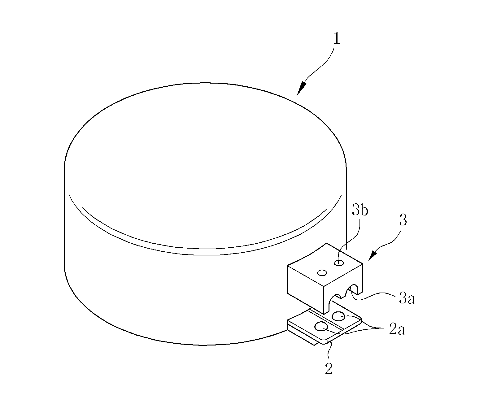
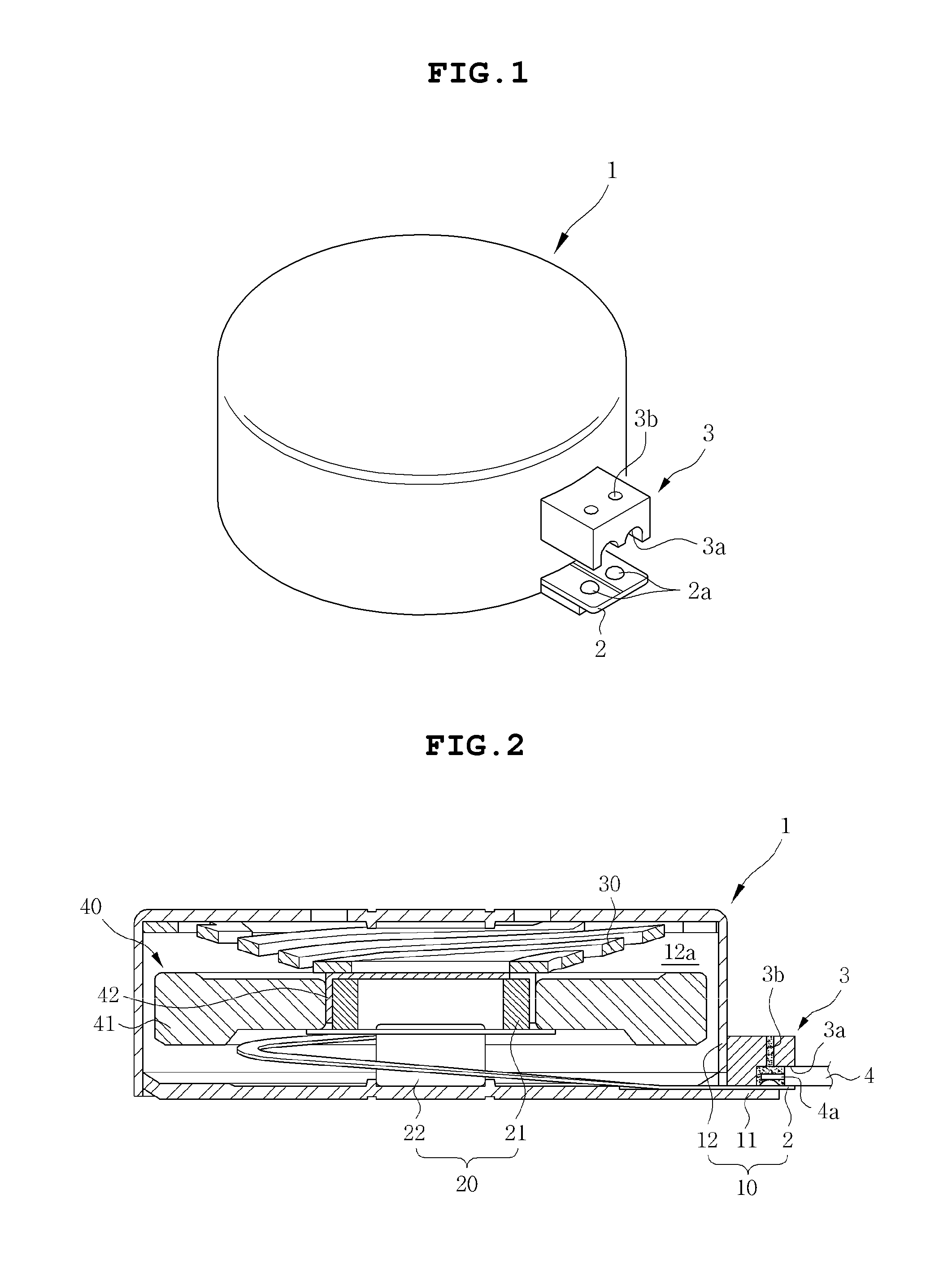
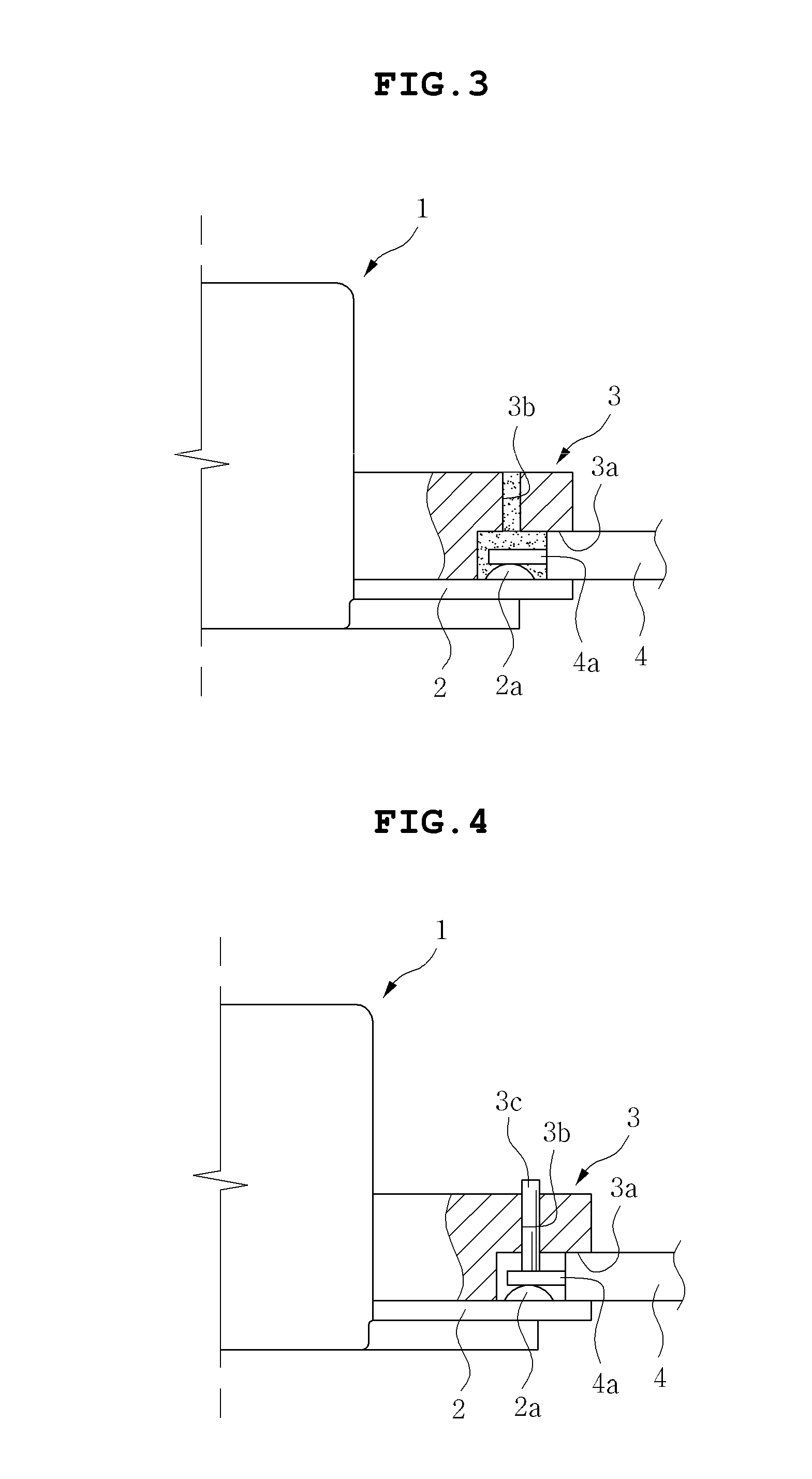
The patent text describes a problem in the connection between an external power source and a vibration motor in the prior art. The position of the terminal part of the lead wire or flexible printed circuit board may change, which can degrade the reliability of the connection. The prior art also suggests a soldering method that degrades workability. The present invention provides a solution by installing a standardized connecter to the input terminal of the vibration motor to maintain constant connection quality between the input terminal and a subsidiary material for connecting an external power source. This improves the reliability and ease of connection between the external power source and the vibration motor.

Problems solved by technology

However, in connection between an external power source and a vibration motor disclosed in the prior art including Patent Document 1, the case in which a position of a terminal part of a lead wire or a flexible printed circuit board, which is a subsidiary material, is changed may be generated, such that a soldering standard may not be satisfied.
That is, according to the prior art, since soldering is performed in a state in which the lead wire or the terminal part of the flexible printed circuit board is simply disposed on an input terminal of the vibration motor and overlapped with the input terminal, positions of the input terminal and the lead wire or the terminal part may frequently deviate from each other, which may degrade reliability associated with connection of an external power source.

Method used


Image

  • Vibration motor
  • Vibration motor
  • Vibration motor

Examples


Embodiment Construction

[0026]The objects, features and advantages of the present invention will be more clearly understood from the following detailed description of the preferred embodiments taken in conjunction with the accompanying drawings. Throughout the accompanying drawings, the same reference numerals are used to designate the same or similar components, and redundant descriptions thereof are omitted. Further, in the following description, the terms “first”, “second”, “one side”, “the other side” and the like are used to differentiate a certain component from other components, but the configuration of such components should not be construed to be limited by the terms. Further, in the description of the present invention, when it is determined that the detailed description of the related art would obscure the gist of the present invention, the description thereof will be omitted.

[0027]Hereinafter, preferred embodiments of the present invention will be described in detail with reference to the attac...


PUM


Abstract

Disclosed herein is a vibration motor. In the vibration motor according to the present invention, an external power source is connected by a method of using a connecter, which is an improved method of a soldering method according to the prior art, such that accurate assembling, stable maintenance, and stabilization may be performed. Therefore, a yield for connecting the external power source to the vibration motor may be improved, and a work time may be significantly reduced.

Description

CROSS REFERENCE TO RELATED ED APPLICATION[0001]This application claims the benefit of Korean Patent Application No. 10-2011-0144916, filed on Dec. 28, 2011, entitled “Vibration Motor”, which is hereby incorporated by reference in its entirety into this application.BACKGROUND OF THE INVENTION[0002]1. Technical Field[0003]The present invention relates to a vibration motor.[0004]2. Description of the Related Art[0005]A vibration motor, which is a component converting electrical energy into mechanical vibration using a principle of generating electromagnetic force, is generally mounted in a portable phone, and the like, to generate a silent receiving signal, thereby preventing inconvenience to other people due to an external sound.[0006]This vibration motor may mainly be divided into a rotary vibration motor and a linear vibration motor, wherein in the case of the rotary vibration motor, a rotor having an unbalanced mass is rotated, thereby generating mechanical vibration. Further, in t...

Claims


Application Information

Patent Timeline
Patent Type & Authority Applications(United States)
IPC IPC(8): H02K33/00
CPCH02K33/18H02K5/225H02K2211/03H02K33/00H05K2201/0326G06F3/045H05K1/0274H05K2201/0317G06F3/03547Y10T428/24942G06F3/041H01B5/14G06F2203/04103
Inventor YOON, AN SOO
Owner SAMSUNG ELECTRO MECHANICS CO LTD
Learn More