Polishing Instrument for Optical Components

a technology of optical components and polishing cloths, applied in the direction of optical surface grinding machines, manufacturing tools, edge grinding machines, etc., can solve the problems of cloth becoming torn or otherwise unusable, and achieve the effect of quick and easy replacement of worn polishing cloths

Inactive Publication Date: 2013-07-04
ZENNI OPTICAL
View PDF9 Cites 0 Cited by
  • Summary
  • Abstract
  • Description
  • Claims
  • Application Information

AI Technical Summary

Benefits of technology

[0007]In the art of inner surface polishing of free form progressive lenses the use of fine polishing cloths supported by flexible sponges presents various challenges. As polishing by cloth may be the last or near last step in lens manufacturing, the polishing cloth must be thin and flexible. A sponge or similar item is needed to press the cloth upon the curved lens. In typical product runs, a cloth may become torn or otherwise unserviceable after polishing just twenty or so lenses. Thus, the present invention presents an important advancement in the art, as workers in the art may now quickly and easily replace worn polishing cloths while reusing sponges and base units.

Problems solved by technology

In the art of inner surface polishing of free form progressive lenses the use of fine polishing cloths supported by flexible sponges presents various challenges.
In typical product runs, a cloth may become torn or otherwise unserviceable after polishing just twenty or so lenses.

Method used


Image

  • Polishing Instrument for Optical Components
  • Polishing Instrument for Optical Components
  • Polishing Instrument for Optical Components

Examples


Embodiment Construction

[0024]The following detailed description is directed to certain specific embodiments of the invention. However, the invention can be embodied in a multitude of different ways as defined and covered by the claims and their equivalents. In this description, reference is made to the drawings wherein like parts are designated with like numerals throughout.

[0025]Unless otherwise noted in this specification or in the claims, all of the terms used in the specification and the claims will have the meanings normally ascribed to these terms by workers in the art.

[0026]Unless the context clearly requires otherwise, throughout the description and the claims, the words “comprise,”“comprising” and the like are to be construed in an inclusive sense as opposed to an exclusive or exhaustive sense; that is to say, in a sense of “including, but not limited to.” Words using the singular or plural number also include the plural or singular number, respectively. Additionally, the words “herein,”“above,”“...


PUM


Abstract

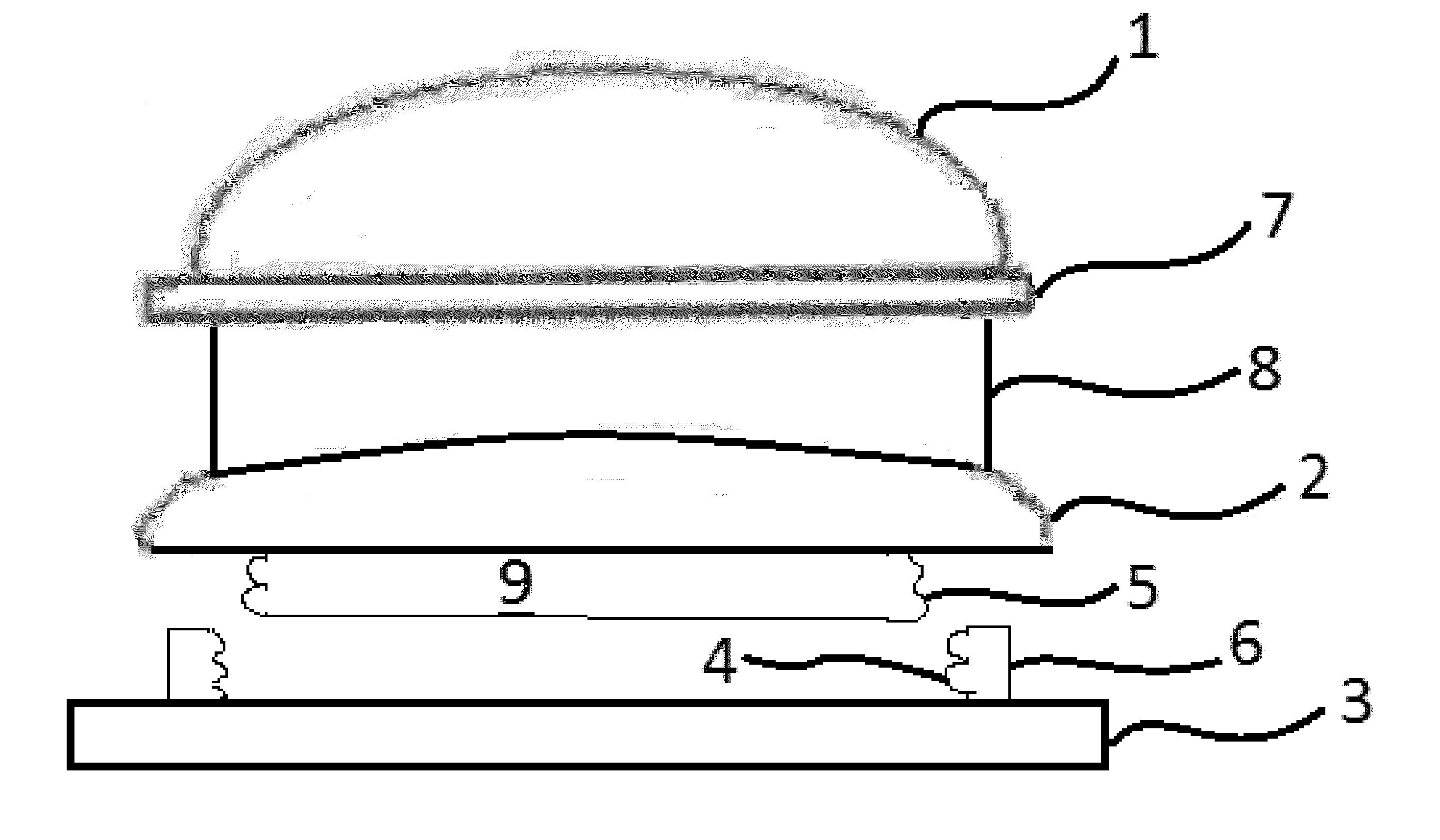
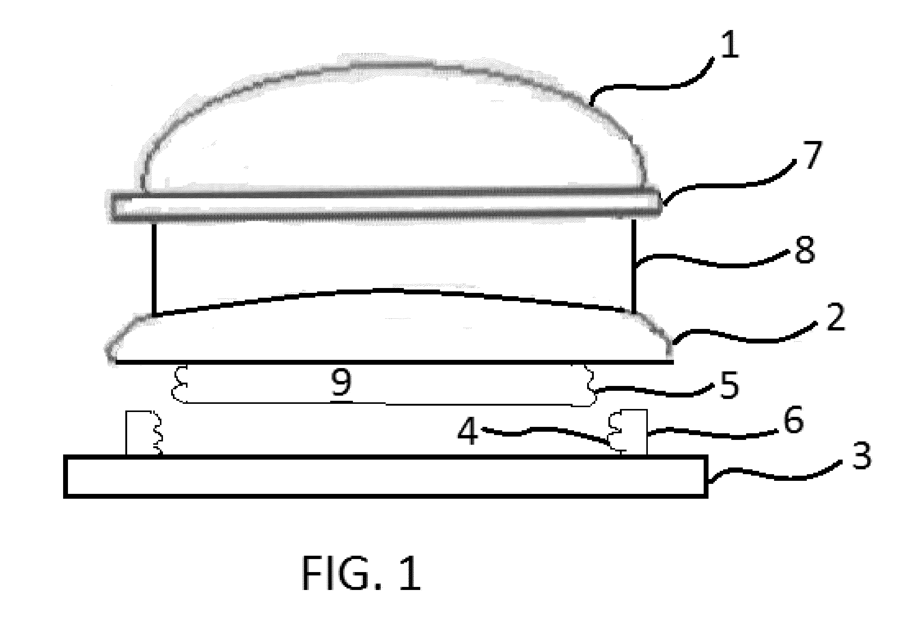
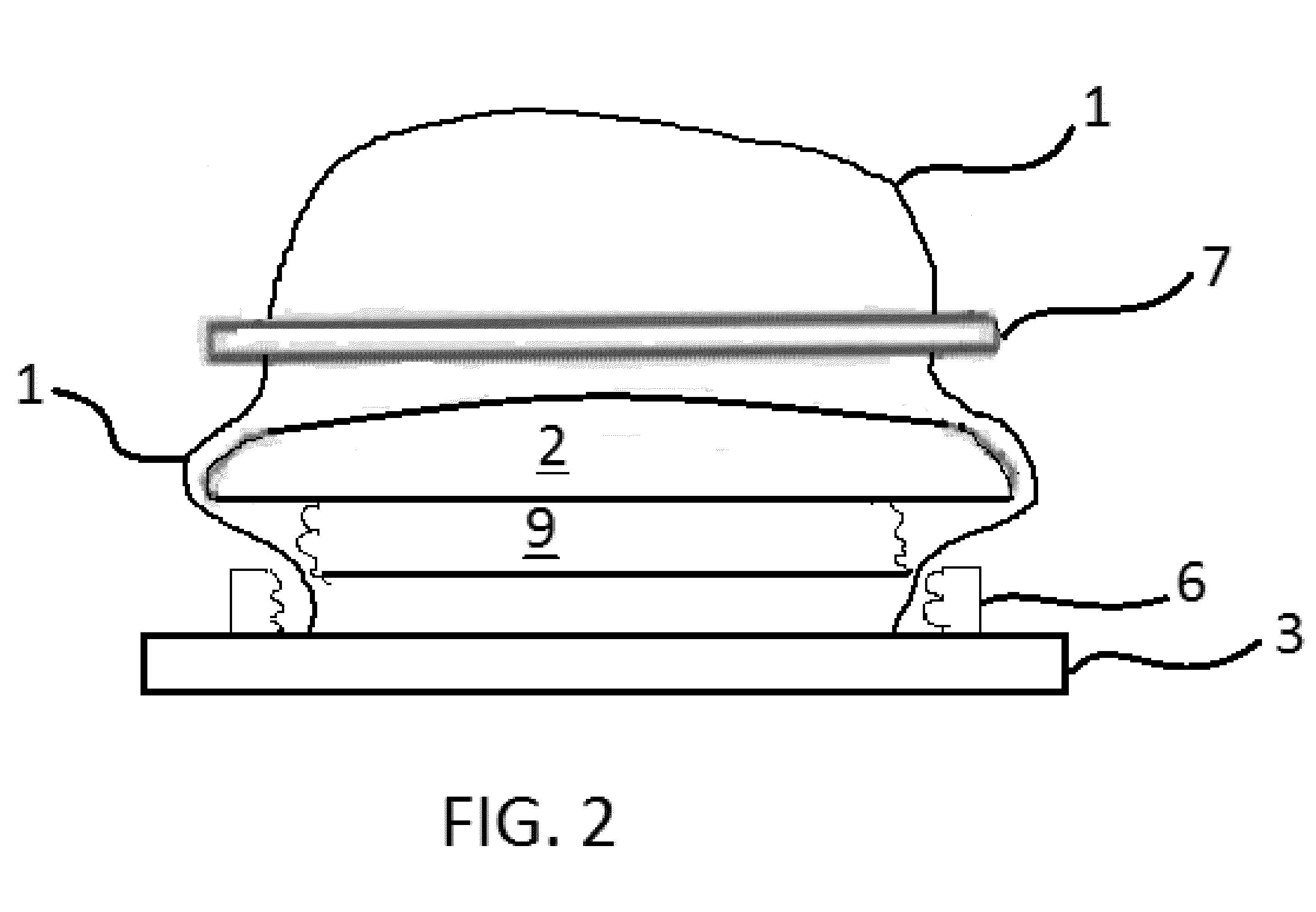
A polishing head that can be disassembled and comprises a polishing cloth 1, sponge 2 and plastic base 3. The polishing cloth 1 is tightly pressed on the plastic base 3 by a sponge 2. The plastic base 3 is divided into one part with male threads and the other part with female threads. The two parts coordinate with each other to achieve dismantling or locking of the cloth and sponge to the base. When the polishing cloth is damaged, the plastic base can be unscrewed to change the damaged polishing cloth, while the base can be reused so as to reduce waste.

Description

BACKGROUND OF THE INVENTION[0001](1) Field of the Invention[0002]The invention generally relates to means and methods of polishing optic lenses and other objects. More particularly, the invention relates to a device that artfully holds a polishing cloth to a sponge by use of a threaded base.[0003](2) The Related Art[0004]In the related art, polishing devices comprise a polishing cloth permanently fixed to a base. During typical product runs wherein many lenses are polished, polishing clothes will become damaged requiring replacement of the entire unit. The related art fails to provide fast and economical means to replace polishing cloths while reusing the bases or related parts such as sponges.BRIEF SUMMARY OF THE INVENTION[0005]The present invention overcomes shortfalls in the related art by presenting an unobvious and unique combination, configuration of components to construct a device that holds a polishing cloth to a sponge and base such that a damaged polishing cloth may be qu...

Claims


Application Information

Patent Timeline
Patent Type & Authority Applications(United States)
IPC IPC(8): B24B27/00
CPCB24B13/012Y10S451/921B24B13/02B24B13/01
Inventor JIAN, SHIZHIGANG, ZHAO
Owner ZENNI OPTICAL
Why Eureka
Try Eureka