Tool holder for cutting insert

a technology for cutting inserts and tools, which is applied to cutting inserts, turning machine accessories, metal-working apparatuses, etc., can solve the problems of reducing the fastening force, requiring a large force to remove the force, and affecting the work efficiency of workers, so as to improve work efficiency, quick and easy replacement of cutting bodies, and easy mounting and separation of cutting tools

Inactive Publication Date: 2022-01-06
KWON DAE GYU
View PDF0 Cites 0 Cited by
  • Summary
  • Abstract
  • Description
  • Claims
  • Application Information

AI Technical Summary

Benefits of technology

[0016]According to the tool holder for a cutting insert according to the present disclosure, there is an effect that it is possible to quickly and easily replace a cutting body that is worn or needs to be replaced.
[0017]Further, since it is easy to mount and separate a cutting tool on or from a tool mount using a cutting body in an integrated structure of a holder body and the tool mount, even non-skilled people can easily replace various types of cutting tools in accordance with working processes for workpieces even without using a large force.
[0018]Further, since a cutting tool can always be fixed with a predetermined length when it is replaced, there is an effect that it is possible to increase work efficiency.
[0019]Further, since work is made convenient and machining is performed only with minimum tools and manpower, there is an effect that it is possible to reduce the entire manufacturing cost.

Problems solved by technology

The bite receives large load and easily wears when machining workpieces.
Accordingly, a lot of trouble such as a large force is required to remove the force and replace the bite When the bite wears.
Further, When the machining shape of a workpiece is changed, the hit should be replaced with another bite suitable for the work, but such frequent replacement of bites causes a problem of reduction of a fastening force and deterioration of machining efficiency.

Method used


Image

  • Tool holder for cutting insert
  • Tool holder for cutting insert
  • Tool holder for cutting insert

Examples


Embodiment Construction

[0032]Hereinbelow, exemplary embodiments of the present disclosure will be described in detail with reference to the accompanying drawings. Throughout the drawings, the same reference numerals will refer to the same or like parts.

[0033]An embodiment is described hereafter in detail with reference to the drawings to achieve the objectives.

[0034]Although a cutting insert is exemplified as a cutting tool in the following description of an embodiment of the present disclosure, the present disclosure is not limited thereto and any tools, such as a bite, a cutter, and a drill, may be applied as long as they can be mounted and used on a tool holder 10.

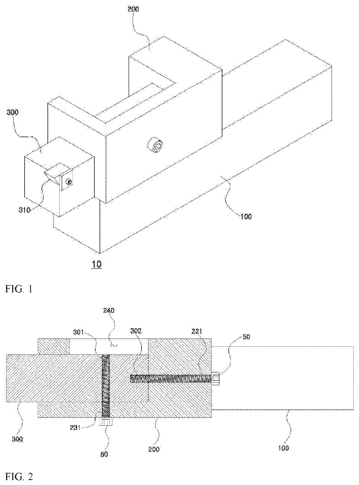
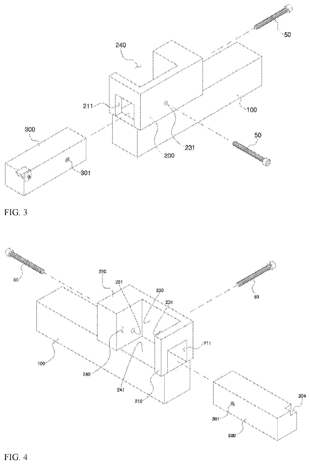
[0035]As shown in FIGS. 1 to 4, a tool holder 10 for a cutting insert according to the present disclosure is configured such that a cutting body 300 combined with a cutting insert is easily attached / detached to / from a tool mount 200 and accurate machining adjustment, that is, calibration for a workpiece is possible when the cutting insert is ...


PUM


Abstract

A tool holder for a cutting insert is proposed, the tool holder being configured to make it possible to easily mount and separate only an insert that is worn during cutting or needs to be replaced for various types of machining, make it possible to easily replace a cutting insert when replacing the cutting insert, and have a coupling structure that enables replacement of even a cutting body on which a cutting insert is mounted.

Description

CROSS REFERENCE TO RELATED APPLICATION[0001]The present application claims priority to Korean Patent Application No. 10-2020-0082918, filed Jul. 6, 2020, the entire contents of which is incorporated herein for all purposes by this reference.BACKGROUNDField[0002]The present disclosure relates to a tool holder for mounting a cutting insert and, more particularly, to a tool holder for a cutting insert, the tool holder being configured to make it possible to easily mount and separate only an insert that is worn during cutting or needs to be replaced for various types of machining, make it possible to easily replace a cutting insert when replacing the cutting insert, and have a coupling structure that enables replacement of even a cutting be on which a cutting insert is mounted.Description of the Related Art[0003]In general, a lathe, which machines rotating workpieces with cutting tools, can be considered as a representative machine tool that was developed first to usually make it possib...

Claims


Application Information

Patent Timeline
Patent Type & Authority Applications(United States)
IPC IPC(8): B23B29/12B23B29/06B23B29/08
CPCB23B29/12B23B29/06B23B2205/10B23B2205/04B23B29/08B23B29/046B23B27/148B23B27/1603
Inventor KWON, DAE GYUKANG, SANG WOO
Owner KWON DAE GYU
Why Eureka
Try Eureka