Geo-mapping system security events

a geomapping system and security event technology, applied in the field of data analytics, can solve the problems of not only but all but the most sophisticated users, and the complexity of managing the functionality of some security tools has become too complex

Active Publication Date: 2013-07-04
MCAFEE LLC
View PDF5 Cites 135 Cited by
  • Summary
  • Abstract
  • Description
  • Claims
  • Application Information

AI Technical Summary

Problems solved by technology

Given the increasing complexity of such tools and the increasing degree to which administrators can customize their security tools to deal with specific threats, including threats unique to particular devices, systems, and applications, managing and understanding the functionality of some security tools has become too complex for all but the most sophisticated of users.
One such example of a security tool that has become notoriously complex to manage is modern network firewalls.

Method used


Image

  • Geo-mapping system security events
  • Geo-mapping system security events
  • Geo-mapping system security events

Examples


example embodiments

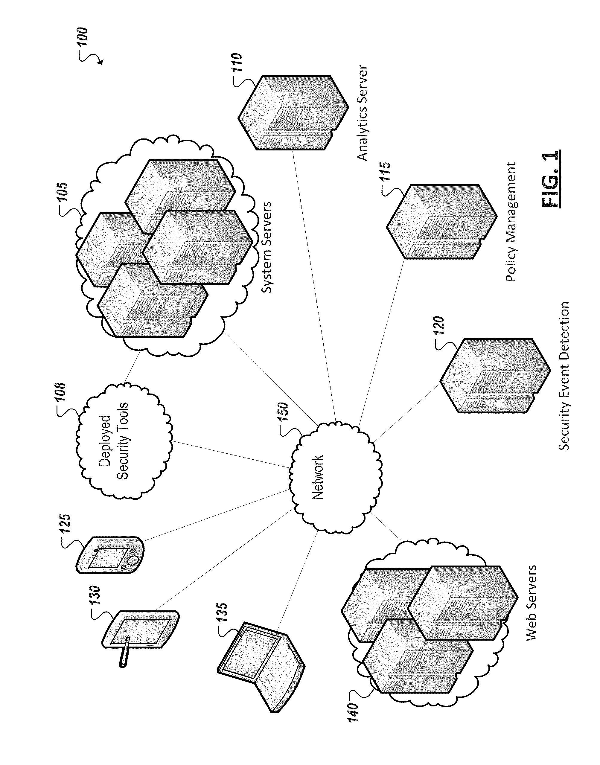
[0016]FIG. 1 is a simplified block diagram illustrating an example implementation of a computing system 100 including a system of computing devices (e.g., 105, 125, 130, 135) monitored by one or more security tools 108. Some of these security tools 108 can be resident on system servers 105, networks, network interfaces, and devices 125, 130, 135, while other security tools 108 can be provided as services, for instance, using computing devices and infrastructure remote from the system servers 105 monitored by the tools. System 100 can further include an analytics server 110, policy management server 115, and security event detection server 120 provided in connection with one or more security tools 108 monitoring system servers 105. User endpoint devices (e.g., 125, 130, 135) can also be provided in system 100. In some instances, one or more endpoint devices (e.g., 125, 130, 135) can interact with and consume services and resources hosted by system servers 105 as well as other servers...


PUM


Abstract

A particular security event is identified that has been detected as targeting a particular computing device included in a particular computing system. A particular grouping of assets in a plurality of asset groupings within the particular computing system is identified as including the particular computing device. A source of the particular security event is also identified and at least one of a geographic location and a grouping of assets in the plurality of asset groupings is associated with the identified source. Data is generated that is adapted to cause a presentation of a graphical representation of the particular security event on a display device, the graphical representation including a first graphical element representing the particular computing device as included in the particular grouping of assets and a second graphical element representing the source associated with the at least one of a geographic location and a grouping of assets.

Description

TECHNICAL FIELD[0001]This disclosure relates in general to the field of data analytics and, more particularly, to graphical user interfaces in data analytics software.BACKGROUND[0002]Computer security tools have been deployed throughout the world to assist in protecting computing systems, devices, and resources from various threats, vulnerabilities, and risks. The evolution of malware, viruses, worms, system vulnerabilities, hacks, and threats originating from a continually-growing and internationalized universe of sources continues to keep pace with the advances in computing. Accordingly, demand for robust and sophisticated security tools to counteract such threats has also increased. Given the increasing complexity of such tools and the increasing degree to which administrators can customize their security tools to deal with specific threats, including threats unique to particular devices, systems, and applications, managing and understanding the functionality of some security too...

Claims


Application Information

Patent Timeline
Patent Type & Authority Applications(United States)
IPC IPC(8): G06F21/00
CPCH04L41/0893H04L41/12H04L63/20H04L41/22G06F21/56H04L41/00H04L41/06G06F16/29H04L67/52G06F21/50G06F2221/034G06T11/60H04L63/1416
Inventor PEARCY, DEREK PATTONHEINRICH, JESSICA ANNEGASKINS, JESSICA JEANNE
Owner MCAFEE LLC
Why Eureka
Try Eureka