
Mounting structure for battery and fuel tank of gasoline-electric hybrid vehicle

Active Publication Date: 2013-07-11
SUBARU CORP
View PDF2 Cites 5 Cited by
  • Summary
  • Abstract
  • Description
  • Claims
  • Application Information

AI Technical Summary

Benefits of technology

The invention is a mounting structure for a battery and fuel tank in a gasoline-electric hybrid vehicle. By placing the battery on one side of the propeller shaft and the fuel tank on the other side, the vehicle's body can be modified minimally. The placement of the battery and fuel tank also allows for increased space in the cabin and trunk compartment, and lowers the vehicle's center of gravity. Additionally, the battery and fuel tank are protected against damage from collisions and refueling spills. Overall, the invention enables a more flexible and safe design for gasoline-electric hybrid vehicles.

Problems solved by technology

In a gasoline-electric hybrid vehicle, which uses both an engine and an electric motor for generating driving power, it is a challenge to ensure a space for mounting a fuel tank and a battery.
However, when a battery is disposed on the back side of the rear seat, the depth dimension of the cargo space is reduced, and thus seat arrangement such as a “trunk through” cannot be made by folding down the back rest of the rear seat.
In the case where the battery is disposed under the floor of the cargo space, loading and unloading a cargo tends to be difficult due to the raised floor surface, and a sufficient height for a cargo cannot be ensured.
In order to ensure the height for a cargo, a solution such as raising the floor surface of the trunk is necessary, and thus a significant restriction in design of a hybrid vehicle is imposed and it is difficult to ensure a driver's view at the same time.
In addition, the technology described in JP-A No. 2000-247261 is directed to an electric vehicle, which is driven only by an electric motor, and does not consider a vehicle structure that has a fuel tank.
Furthermore, in the case where a gasoline engine vehicle and a hybrid vehicle are produced as variations from a common platform, designing two types of floor panel separately increases the number of development steps and investment of production facility

Method used


Image

  • Mounting structure for battery and fuel tank of gasoline-electric hybrid vehicle
  • Mounting structure for battery and fuel tank of gasoline-electric hybrid vehicle
  • Mounting structure for battery and fuel tank of gasoline-electric hybrid vehicle

Examples


embodiments

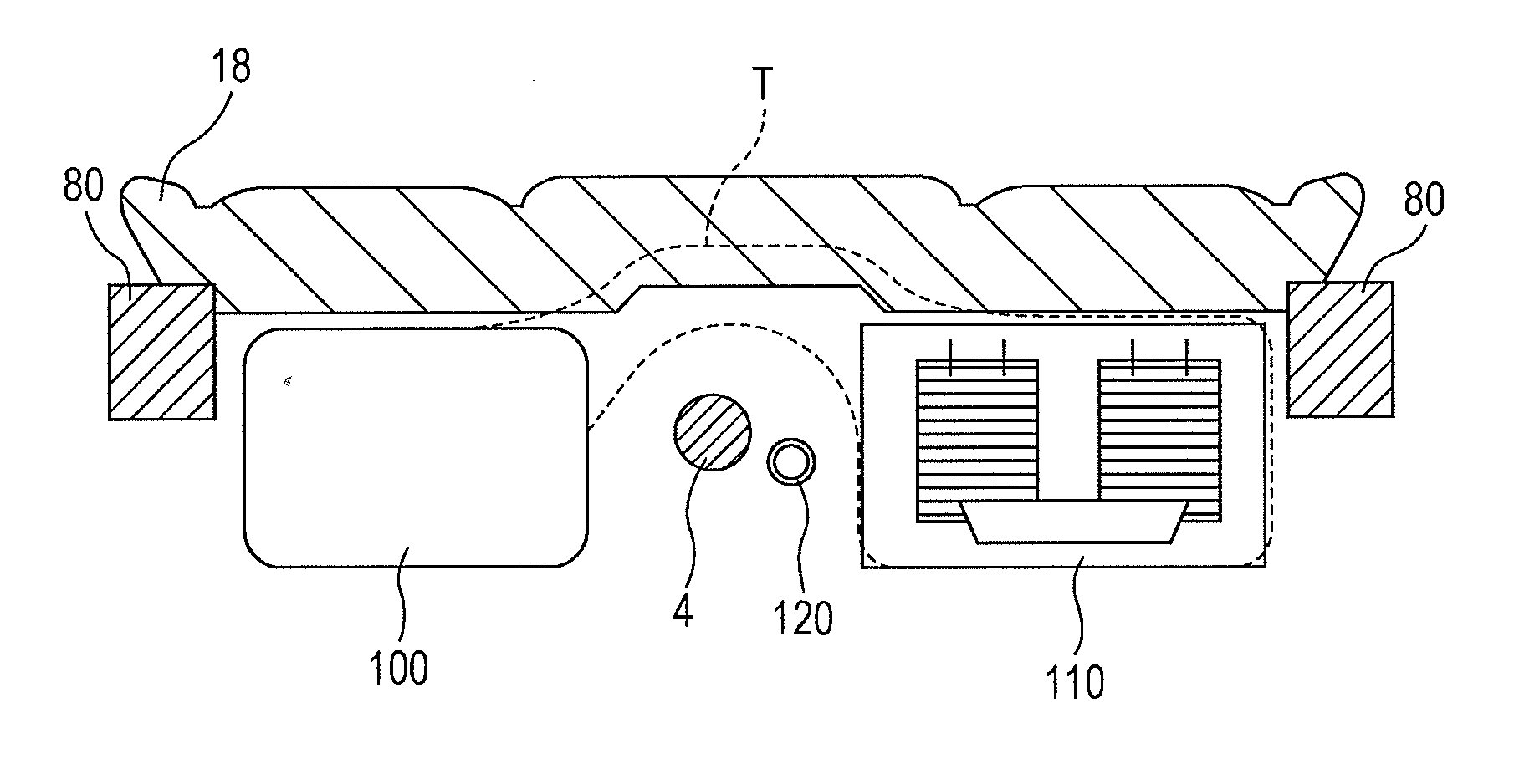
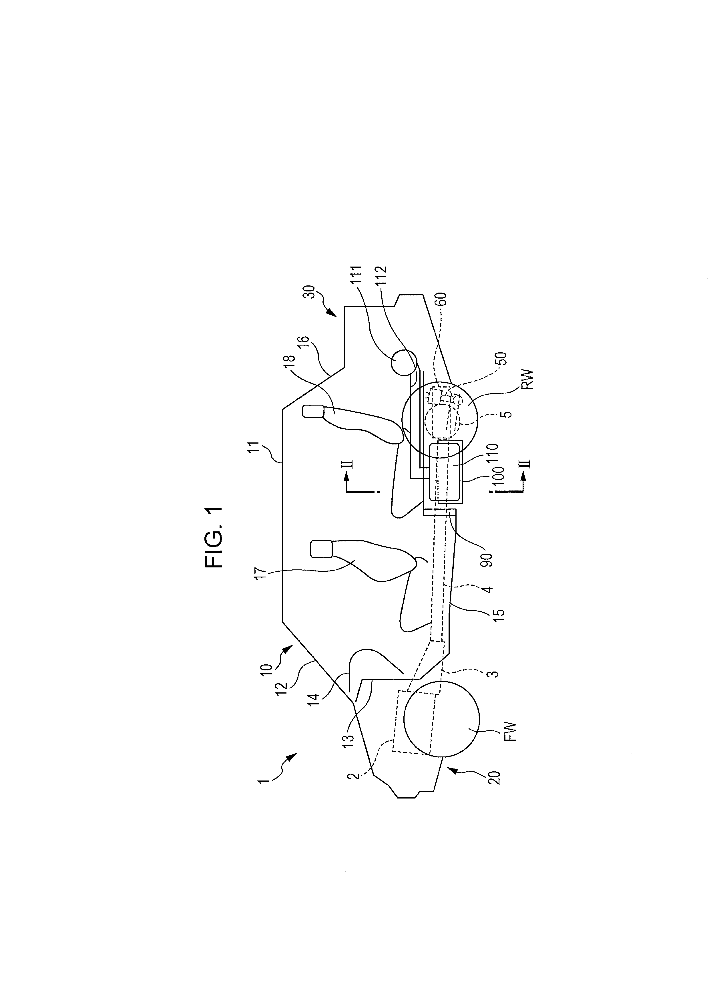
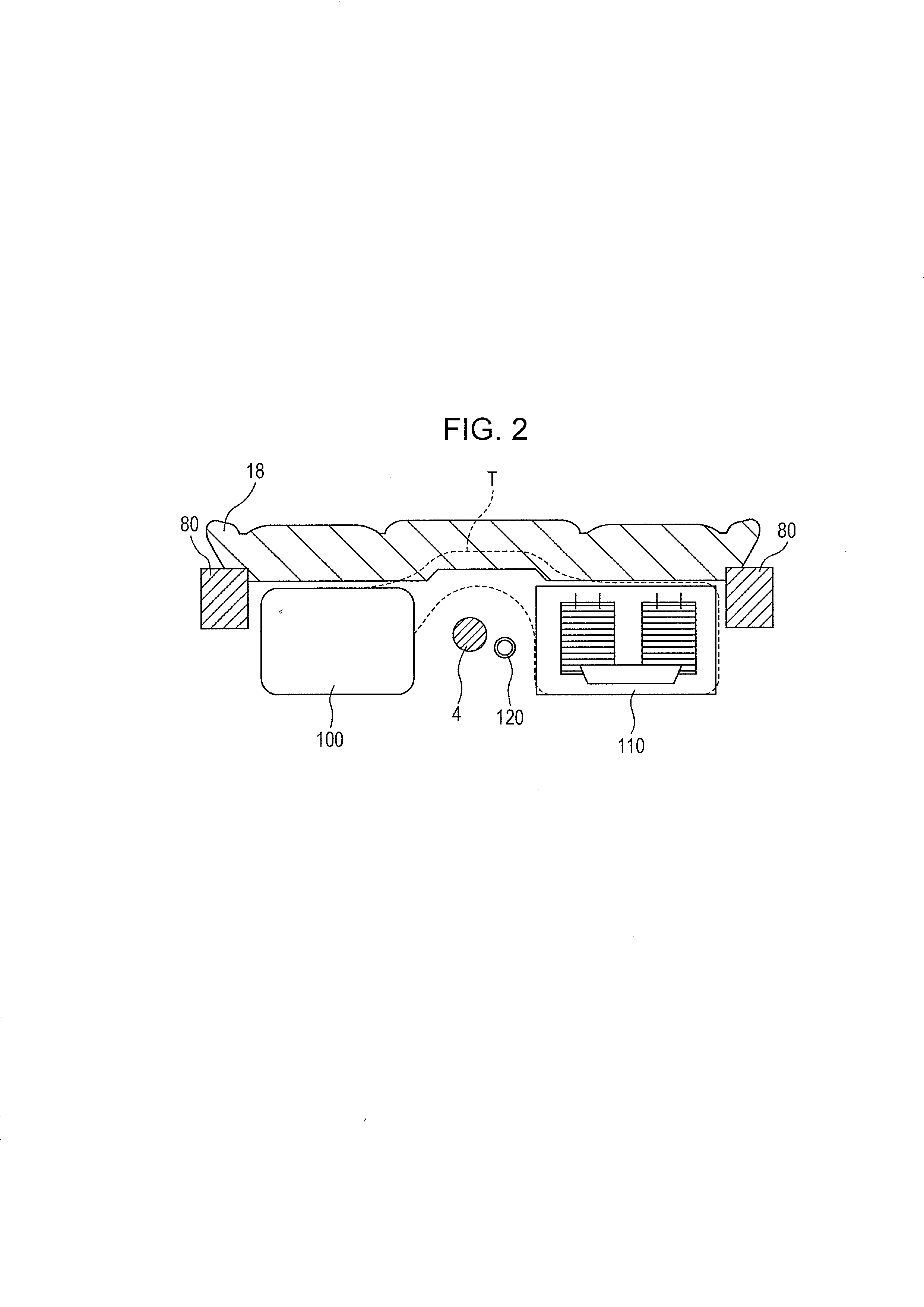
[0016]Hereinafter, an embodiment of a mounting structure for a battery and a fuel tank of a gasoline-electric hybrid vehicle according to the present invention will be described. FIG. 1 is a schematic perspective side view of s vehicle. FIG. 2 is a schematic cross-sectional view taken along the line II-II of FIG. 1. FIG. 3 is a schematic plan view from below of the floor of the vehicle of FIG. 1. A vehicle 1 to which the mounting structure for a battery and a fuel tank according to the embodiment is applied is, for example, a gasoline-electric hybrid vehicle that uses both a gasoline engine and an electric motor for generating driving power, and can perform regenerative power generation by using the electric motor as a generator. The vehicle 1 is, for example, a three-box sedan having an engine compartment 20 and a trunk compartment 30 in front and rear of a passenger space (cabin) 10, respectively. The vehicle 1 is an all-wheel drive (AWD) vehicle that has an engine 2 and a transmi...


PUM


Abstract

There is provided a mounting structure for a battery and a fuel tank of a gasoline-electric hybrid vehicle. The mounting structure allows the battery to be disposed on one side of a propeller shaft, and the fuel tank to be disposed on the other side of the propeller shaft. The propeller shaft is disposed in the center of the vehicle and below the bearing surface of the rear seat, under the floor of the vehicle body so as to substantially extend in the fore-aft direction of the vehicle.

Description

CROSS-REFERENCE TO RELATED APPLICATIONS[0001]The present application claims priority from Japanese Patent Application No. 2012-001182 filed on Jan. 6, 2012, the entire contents of which are hereby incorporated by reference.BACKGROUND OF THE INVENTION[0002]1. Field of the Invention[0003]The present invention relates to a mounting structure for a battery and a fuel tank of a gasoline-electric hybrid vehicle, and particularly to a mounting structure that can be implemented even for a gasoline-electric hybrid vehicle having a propeller shaft, the mounting structure allowing the vehicle to provide a cabin and / or cargo space, to have the center of gravity at a low position, and to use parts commonly used in a gasoline engine vehicle.[0004]2. Description of the Related Art[0005]In a gasoline-electric hybrid vehicle, which uses both an engine and an electric motor for generating driving power, it is a challenge to ensure a space for mounting a fuel tank and a battery. Conventionally, there ...

Claims


Application Information

Patent Timeline
IPC IPC(8): F02B77/00
CPCF02B77/00B60K1/04B60K13/04B60K15/063B60K2001/005B60K17/34B60K2001/0433B60K2015/0633B60K11/06B60K17/22
Inventor MATSUDA, HIROSHI
Owner SUBARU CORP
Learn More