Microscope and microscope light source unit
a light source unit and microscope technology, applied in the field of microscope light source units, can solve problems such as affecting observation
- Summary
- Abstract
- Description
- Claims
- Application Information
AI Technical Summary
Benefits of technology
Problems solved by technology
Method used
Image
Examples
embodiment 1
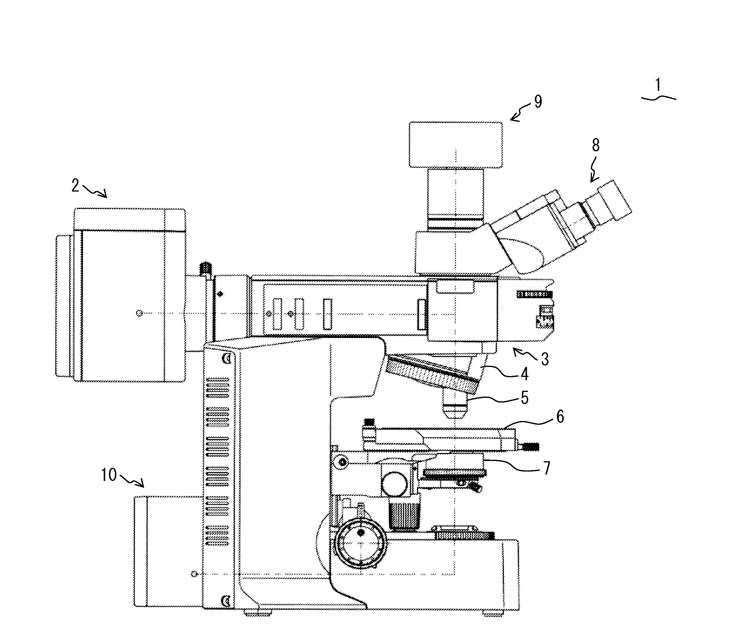
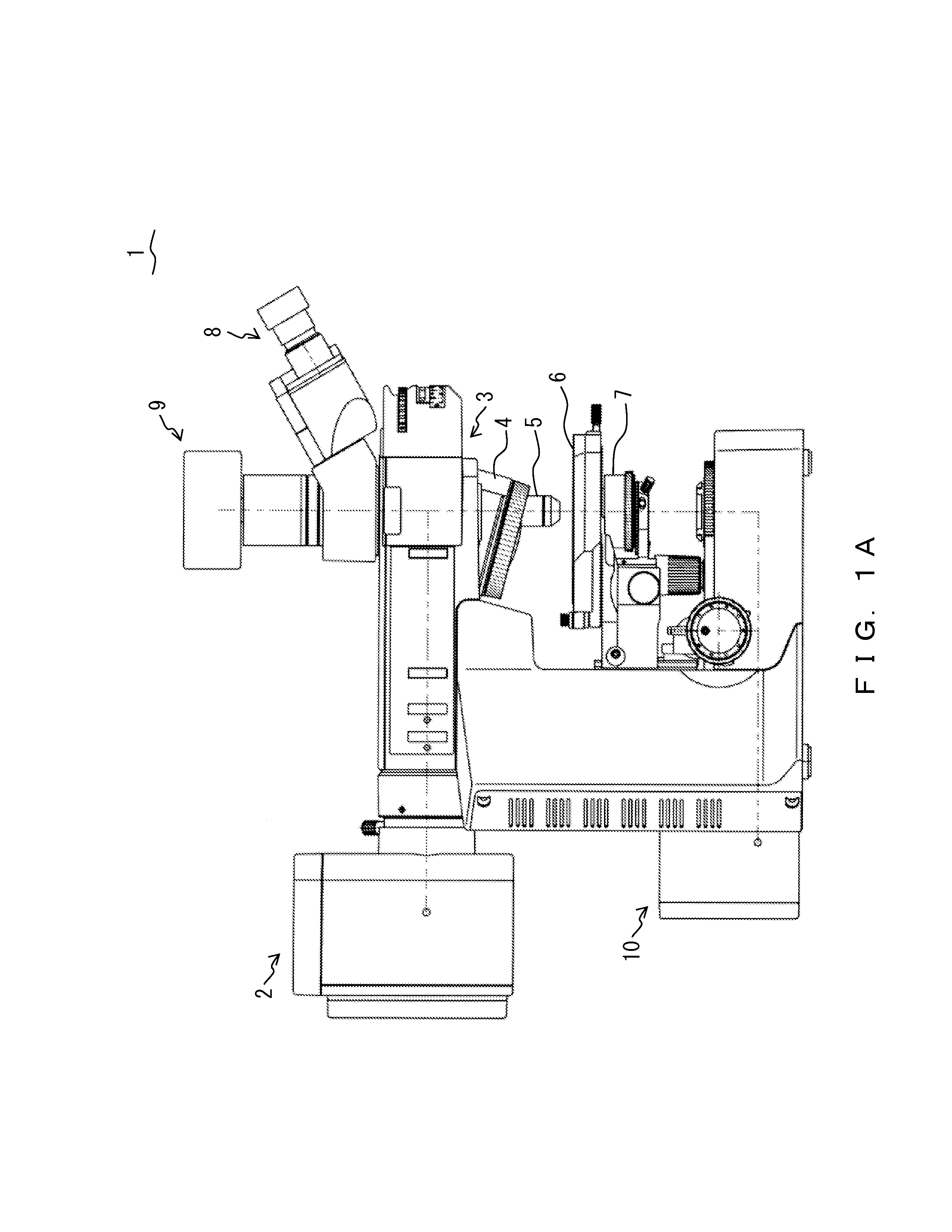
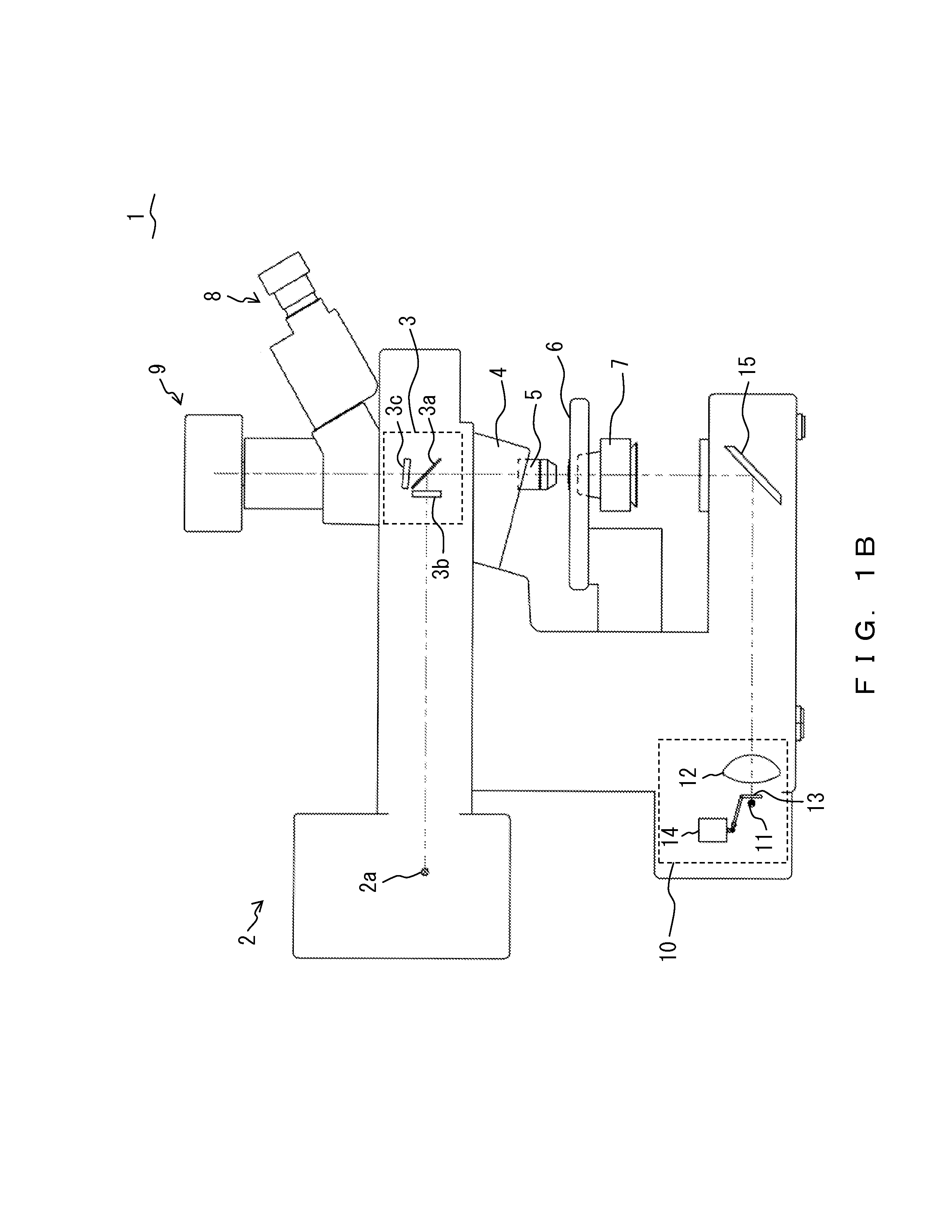
[0045]FIG. 3A illustrates a configuration of a light source unit that includes a light emitting element and a fluorescent substance in accordance with the present embodiment and illustrates a state which is achieved during a light-off period of the light emitting element. FIG. 3B illustrates the configuration of the light source unit that includes the light emitting element and the fluorescent substance in accordance with the present embodiment and illustrates a state which is achieved during a light-on period of the light emitting element. Except for the fact that the microscope in accordance with the present embodiment includes alight source unit 20 illustrated in FIG. 3A and FIG. 3B instead of the light source unit 10, the microscope in accordance with the present embodiment is similar to the microscope 1 illustrated in FIG. 1A and FIG. 1B. Accordingly, descriptions will not be given in detail.
[0046]The light source unit 20 illustrated in FIG. 3A and FIG. 3B is a microscope light...
embodiment 2
[0051]FIG. 4A illustrates a configuration of a light source unit that includes a light emitting element and a fluorescent substance in accordance with the present embodiment and illustrates a state which is achieved during a light-off period of the light emitting element. FIG. 4B illustrates the configuration of the light source unit that includes the light emitting element and the fluorescent substance in accordance with the present embodiment and illustrates a state which is achieved during a light-on period of the light emitting element. Except for the fact that the microscope in accordance with the present embodiment includes alight source unit 30 illustrated in FIG. 4A and FIG. 4B instead of the light source unit 10, the microscope in accordance with the present embodiment is similar to the microscope 1 illustrated in FIG. 1A and FIG. 1B. Accordingly, descriptions will not be given in detail.
[0052]The light source unit 30 illustrated in FIG. 4A and FIG. 4B is a microscope light...
embodiment 3
[0059]FIG. 6A illustrates a configuration of a light source unit that includes a light emitting element and a fluorescent substance in accordance with the present embodiment and illustrates a state which is achieved during a light-off period of the light emitting element. FIG. 6B illustrates the configuration of the light source unit that includes the light emitting element and the fluorescent substance in accordance with the present embodiment and illustrates a state which is achieved during a light-on period of the light emitting element. Except for the fact that the microscope in accordance with the present embodiment includes a light source unit 50 illustrated in FIG. 6A and FIG. 6B instead of the light source unit 10, the microscope in accordance with the present embodiment is similar to the microscope 1 illustrated in FIG. 1A and FIG. 1B. Accordingly, descriptions will not be given in detail.
[0060]The light source unit 50 illustrated in FIG. 6A and FIG. 6B is a microscope ligh...
PUM
 Abstract
Description
Claims
Application Information
 - R&D
- Intellectual Property
- Life Sciences
- Materials
- Tech Scout
- Unparalleled Data Quality
- Higher Quality Content
- 60% Fewer Hallucinations
Browse by: Latest US Patents, China's latest patents, Technical Efficacy Thesaurus, Application Domain, Technology Topic, Popular Technical Reports.
© 2025 PatSnap. All rights reserved.Legal|Privacy policy|Modern Slavery Act Transparency Statement|Sitemap|About US| Contact US: help@patsnap.com


