Visual inspection apparatus

A technology of appearance inspection device and observation device, which is applied to measurement devices, optical testing flaws/defects, instruments, etc., can solve the problems of inability to observe, unable to obtain images, and narrow observable range.

Inactive Publication Date: 2008-10-01
OLYMPUS CORP
View PDF1 Cites 5 Cited by
  • Summary
  • Abstract
  • Description
  • Claims
  • Application Information

AI Technical Summary

Problems solved by technology

[0004] However, in the existing device structure, it is impossible to obtain an image unless a camera is installed in the bright field range, so the observable range is narrow
[0005] In the conventional lighting unit, it is difficult to brightly illuminate the workpiece in a wide range, so when the camera is moved, observation in the bright field cannot be performed satisfactorily.
[0006] In order to observe and analyze the peripheral part of the workpiece in detail, it is preferable to observe in the dark field, but in the conventional device structure, the observation in the dark field cannot be performed.

Method used


Image

  • Visual inspection apparatus
  • Visual inspection apparatus
  • Visual inspection apparatus

Examples


Embodiment Construction

[0022] The best mode for carrying out the present invention will be described in detail with reference to the drawings. However, the present invention itself is of course not limited to these embodiments.

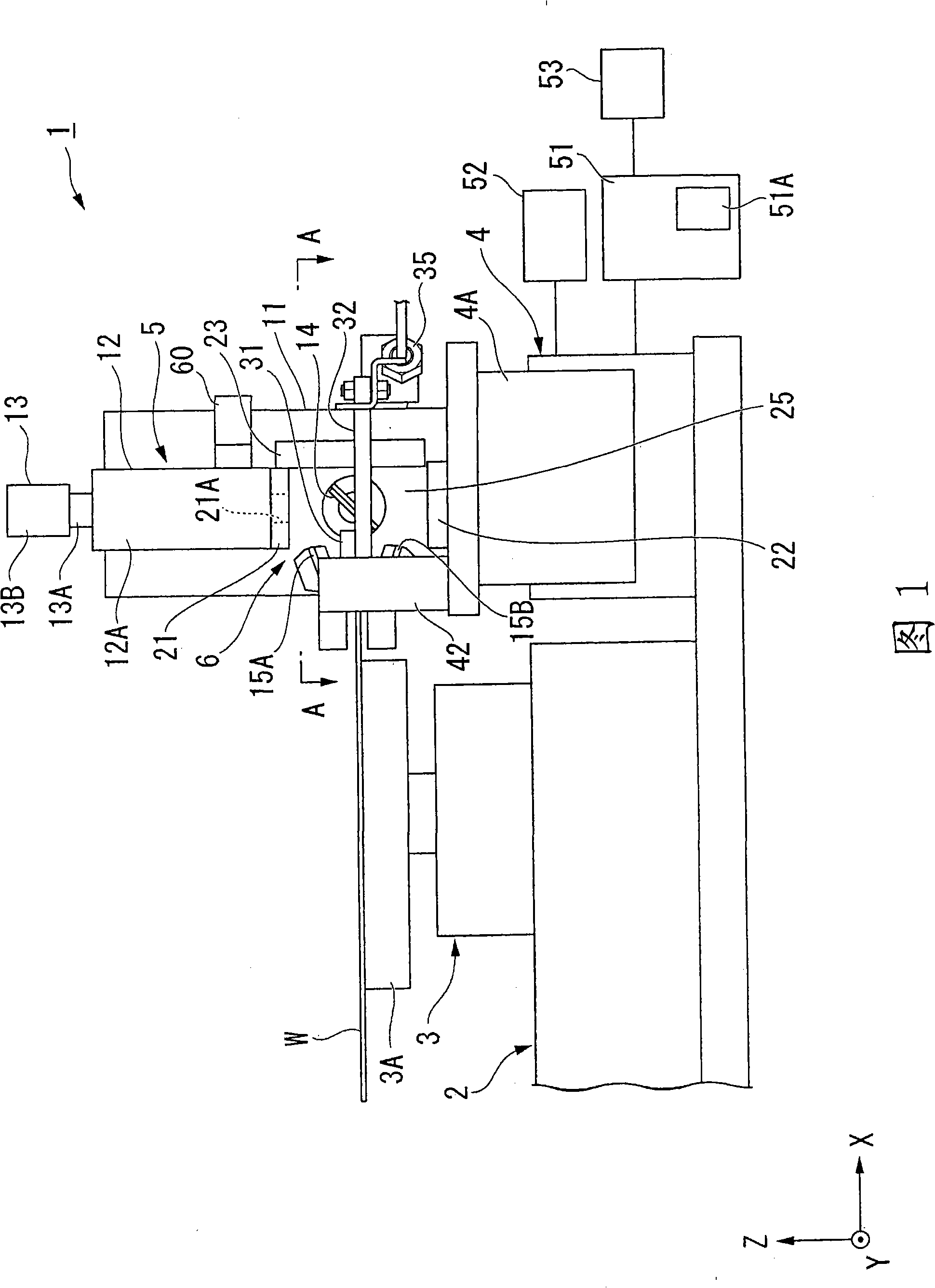
[0023] As shown in FIG. 1 , an appearance inspection apparatus 1 is provided with an XYθ stage 3 and a Z stage 4 on a base 2 for sucking and holding a wafer W which is a workpiece.

[0024] The XYθ stage 3 has a support portion 3A for supporting the wafer W, and a suction portion (not shown) that suction-holds the center of the back surface of the wafer W is provided on the support portion 3A. The XYθ stage 3 is configured so that the support portion 3A can move in two directions (X direction, Y direction) perpendicular to the horizontal direction and can rotate around a Z axis perpendicular to the XY direction. The drive of the XYθ stage 3 is controlled by a motor not shown. As the motor, a motor capable of precise positioning such as a servo motor or a stepping motor is...


PUM


Abstract

A visual inspection apparatus includes an upper illuminator, a lower illuminator, a side illuminator, and a pair of inclined illuminators, which illuminate the peripheral edge of a wafer, and illuminates the peripheral edge of the wafer brightly. A gap is formed in the upper illuminator and illumination light of an epi-illumination portion is injected through the gap. The illumination light of the epi-illumination portion is refracted and reflected by a first mirror to illuminate the peripheral edge of the wafer. The illumination position is changed by moving second mirrors together as needed. An image of the peripheral edge is acquired in an imaging portion disposed at the same axis as the epi-illumination portion.

Description

technical field [0001] The present invention relates to an appearance inspection device for inspecting the appearance of the periphery of workpieces such as wafers. Background technique [0002] When patterns such as circuits are formed on workpieces such as semiconductor wafers, warping or internal stress may occur on the workpieces due to heat treatment. When the warpage of the workpiece or the internal stress increases, the workpiece may crack during the manufacture of the circuit. Therefore, it is known to observe the peripheral part of the workpiece in advance to detect the presence or absence of cracks that may develop into cracks in the future. . [0003] As a device for observing the peripheral portion of the workpiece, for example, as disclosed in Japanese Patent Application Laid-Open No. 2003-243465, there is a device in which a C-shaped lighting unit is provided close to the peripheral portion of the workpiece, and a camera is installed at a position away from th...

Claims


Application Information

Patent Timeline
Patent Type & Authority Applications(China)
IPC IPC(8): H01L21/66G01N21/95
CPCG01N21/9503G01N21/8806
Inventor 横田敦俊仓田俊辅
Owner OLYMPUS CORP
Why Eureka
Try Eureka