Microscope illumination device
a technology of illumination device and microscope, which is applied in the field of microscope illumination device, can solve the problems of small illumination non-uniformity, inconvenient observation, and inability to detect the illumination uniformity,
- Summary
- Abstract
- Description
- Claims
- Application Information
AI Technical Summary
Benefits of technology
Problems solved by technology
Method used
Image
Examples
embodiment 1
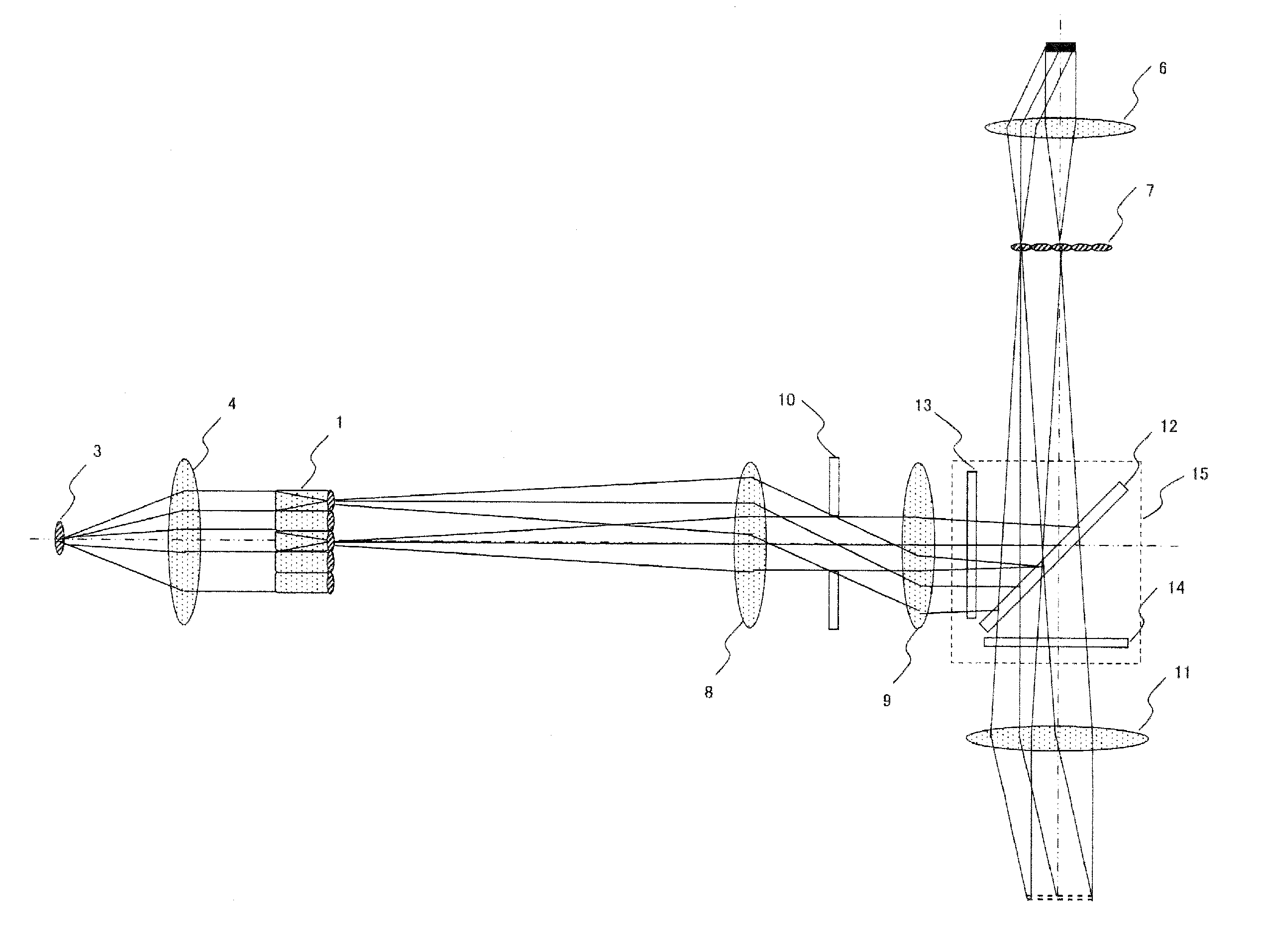
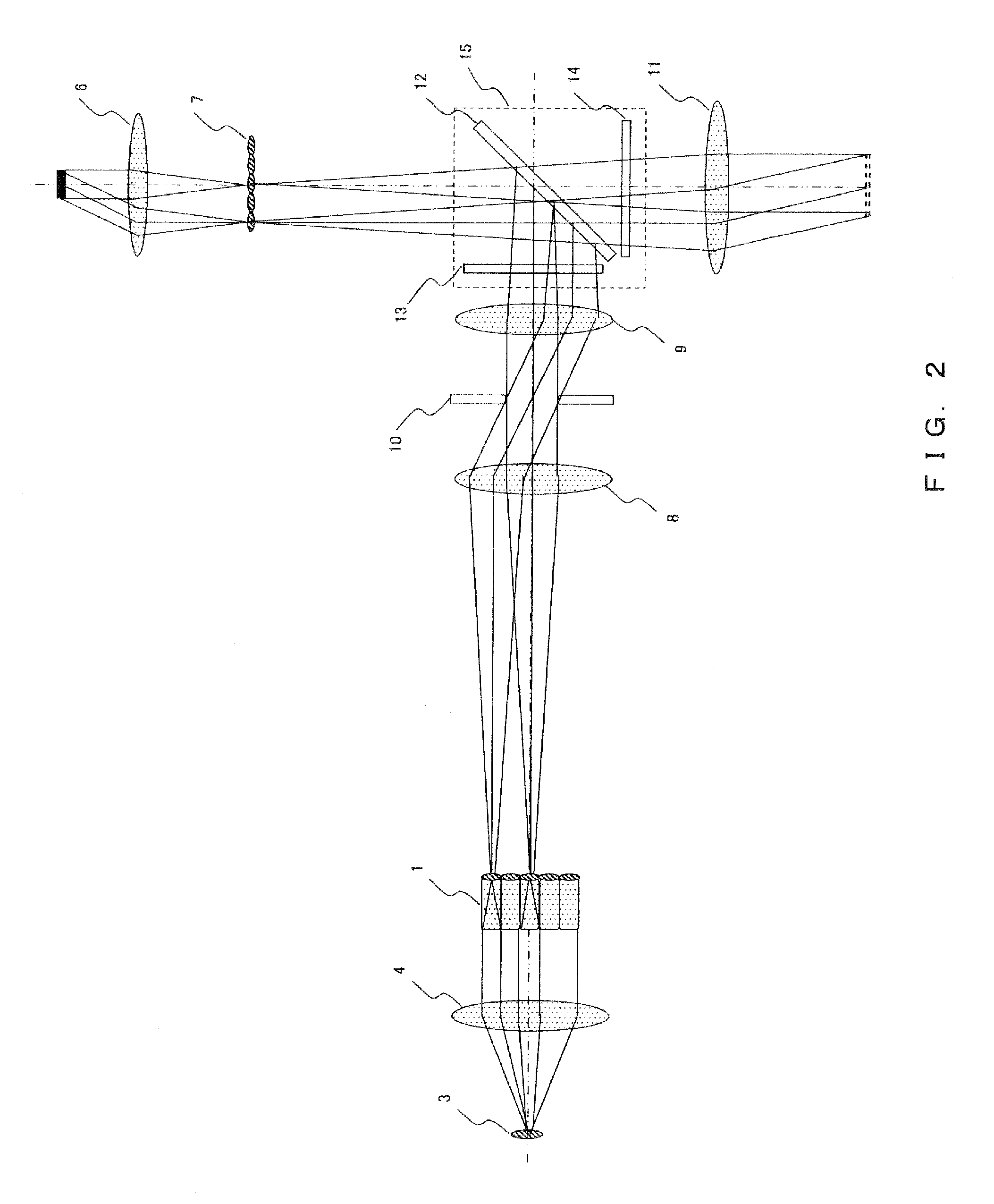
[0056]The numerical value data shown in the following Table 1 premises a microscope illumination device carrying out an epi-illumination using a mercury arc light source in an upright microscope. Note that the magnification ratio of the object lens is assumed to be 10×.
[0057]
TABLE 1Focal distance of collector lensfCL30.0Projection magnification ratio of projectionγ0.70lensNA of ejection side of fly-eye lensNAfly0.050Effective diameter of fly-eye lensD18.0Pitch of fly-eye lensp3.00Focal distance of fly-eye lensffly30.0Magnification ratio of object lensβ10Pupil diameter of object lensq14.4Field number of object lensS26.5Focal distance of object lensfOB18.00Effective diameter of exciter filterφBP22.0Distance from object lens pupil to exciter filterh60.0Maximum diameter of light sourcea0.50
[0058]The present embodiment using these numerical values satisfies the above described expressions (1), (5), (8) and (11).
embodiment 2
[0059]The numerical value data shown in the following Table 2 premises a microscope illumination device carrying out an epi-illumination using a mercury arc light source in an upright microscope. Note that the magnification ratio of the object lens is assumed to be 40×.
[0060]
TABLE 2Focal distance of collector lensfCL6.0Projection magnification ratio of projectionγ0.70lensNA of ejection side of fly-eye lensNAfly0.050Effective diameter of fly-eye lensD8.0Pitch of fly-eye lensp1.50Focal distance of fly-eye lensffly15.0Magnification ratio of object lensβ40Pupil diameter of object lensq8.6Field number of object lensS26.5Focal distance of object lensfOB4.50Effective diameter of exciter filterφBP22.0Distance from object lens pupil to exciter filterh110.0Maximum diameter of light sourcea0.50
[0061]The present embodiment using these numerical values satisfies the above described expressions (1), (5), (8) and (11).
embodiment 3
[0062]The numerical value data shown in the following Table 3 premises a microscope illumination device carrying out an epi-illumination using a mercury arc light source in an inverted microscope. Note that the magnification ratio of the object lens is assumed to be 100×.
[0063]
TABLE 3Focal distance of collector lensfCL10.0Projection magnification ratio of projectionγ1.10lensNA of ejection side of fly-eye lensNAfly0.080Effective diameter of fly-eye lensD4.5Pitch of fly-eye lensp1.60Focal distance of fly-eye lensffly10.0Magnification ratio of object lensβ100Pupil diameter of object lensq5.0Field number of object lensS26.5Focal distance of object lensfOB1.80Effective diameter of exciter filterφBP22.0Distance from object lens pupil to exciter filterh110.0Maximum diameter of light sourcea0.50
[0064]The present embodiment using these numerical values satisfies the above described expressions (1), (5), (8) and (11).
PUM
 Abstract
Description
Claims
Application Information
 - R&D
- Intellectual Property
- Life Sciences
- Materials
- Tech Scout
- Unparalleled Data Quality
- Higher Quality Content
- 60% Fewer Hallucinations
Browse by: Latest US Patents, China's latest patents, Technical Efficacy Thesaurus, Application Domain, Technology Topic, Popular Technical Reports.
© 2025 PatSnap. All rights reserved.Legal|Privacy policy|Modern Slavery Act Transparency Statement|Sitemap|About US| Contact US: help@patsnap.com


