Uniform epi-illumination of planar samples

a planar sample and epi-illumination technology, applied in the field of fluorescence imaging of planar samples, can solve the problems of high non-uniform illumination, correspondingly non-uniform sample signal, and reduction in intensity, so as to reduce the non-uniformity or eliminate the effect of substantially reducing the length of the illuminated area

Inactive Publication Date: 2013-08-29
BIO RAD LAB INC
View PDF2 Cites 5 Cited by
  • Summary
  • Abstract
  • Description
  • Claims
  • Application Information

AI Technical Summary

Benefits of technology

[0004]The present invention stems, at least in part, from the discovery that LED line lights, when used in conjunction with optical bandpass filters, as such lights commonly are, and when placed end-to-end to extend the length of the illuminated area, do not produce a uniform light intensity along their combined lengths. Instead, the intensity produced in the region of the junction between the two line lights is significantly higher than that produced in neighboring regions. It has accordingly been discovered that this nonuniformity can be substantially reduced or eliminated by placing a gap between the two line lights, with no light source within the gap. The result is two adjacent and coaxial line lights separated by a gap, that when placed above a planar sample at a

Problems solved by technology

The illumination produced by LED illuminators is highly non-uniform illumination, however, with a typical radial reduction in intensity of 90% or more from the center of the sample to the edge.
This presents a challenge, because non-uniform sample illumination results in a corresp

Method used


Image

  • Uniform epi-illumination of planar samples
  • Uniform epi-illumination of planar samples
  • Uniform epi-illumination of planar samples

Examples


Embodiment Construction

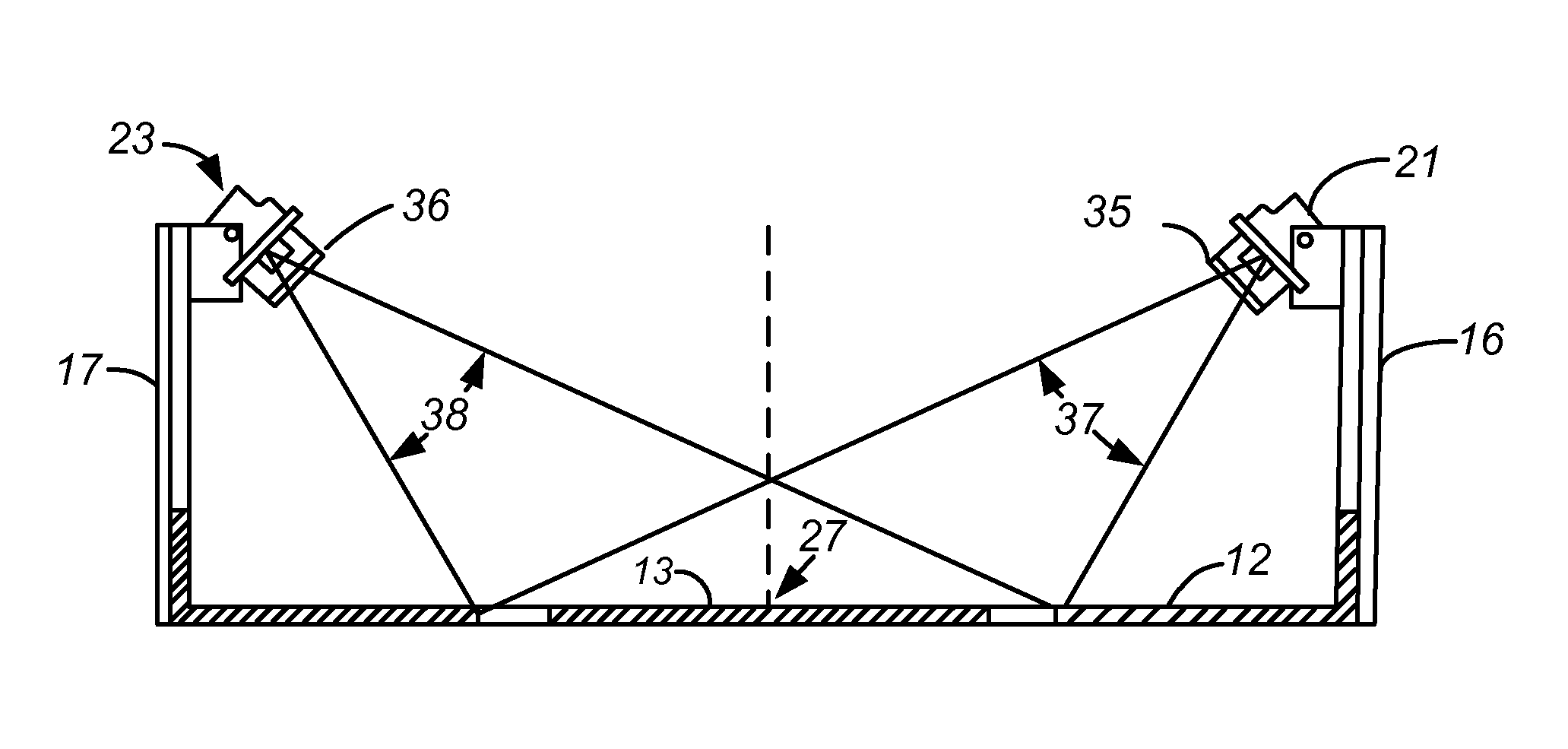
[0010]High-intensity LED line lights are commercially available from a variety of suppliers. Examples are Edmund Optics Inc. of Barrington, N.J., USA, ProPhotonix Limited of Salem, N.H., USA, and Advanced Illumination, Inc., of Rochester, Vt., USA. The typical LED line light is a linear array of individual LEDs evenly spaced with approximately 0.5 mm between each adjacent pair in the array. In certain embodiments of the invention, however, the non-uniform spacings between individual LEDs can be beneficial, for example when significant decreases in intensity (intensity “roll-offs”) occur at the outer ends of the paired line lights. A spacing that decreases in the direction of the outer end can compensate for these decreases to assure that uniformity of intensity continues along the entire combined lengths of the two line lights, in addition to the region of the gap between the two line lights. The variation in spacing is readily determined by routine experimentation.

[0011]The length ...


PUM


Abstract

A planar sample, particularly of the type used in biological laboratories for detection and sometimes analysis of two-dimensional arrays of proteins, nucleic acids, or other biological species, is illuminated by epi-illumination using optically filtered line lights that are arranged along opposing parallel sides of a rectangle in which the sample array resides, with two coaxial line lights on each side of the rectangle, and the two on any given side being separated by a gap whose optimal width depends on the wavelength band transmitted by the optical filter. Surprisingly, the gap eliminates the peak in intensity at the center of the sample area and the decrease that occurs from the center outward that would otherwise occur with a single continuous filtered line light, producing instead a substantially uniform intensity along the direction parallel to the line lights.

Description

CROSS-REFERENCE TO RELATED PATENT APPLICATIONS[0001]The present application claims benefit of priority to U.S. Provisional Patent Application No. 61 / 604,946, filed on Feb. 29, 2012, which is incorporated by reference.BACKGROUND OF THE INVENTION[0002]Studies of DNA and proteins in biological laboratories often involve the fluorescence imaging of planar samples of moderate to large area, such as those ranging from 5 cm×5 cm up to 26 cm×26 cm. Common examples of these samples are electrophoresis gels and blotting membranes. The imaging is often performed by camera-based instruments that include an excitation light source of different wavelengths, depending on the sample matrix and the species sought to be detected within the matrix. Gels for example are substantially transparent to ultraviolet (UV), visible, and near infrared (NIR) light, and can be detected from above with illumination from below in the “trans” mode, i.e., by a transilluminator. Transillumination is typically performe...

Claims


Application Information

Patent Timeline
IPC IPC(8): F21V21/005F21V13/02F21V9/08
CPCF21V21/005F21V9/083F21V13/02G01N2201/0635G01N2021/6463G01N2201/06G01N2201/0626G01N21/6452G01N21/255G01N21/6456G01N2021/6471G01N27/447
Inventor HILLENDAHL, JAMES W.PEREZ, EVELIO
Owner BIO RAD LAB INC
Why Eureka
Try Eureka